Apparatus for propagating optical radiation

a technology of optical radiation and apparatus, applied in the direction of active medium shape and construction, instruments, lasers, etc., can solve the problems of limited work into the development of such arrays and temporal instability

Inactive Publication Date: 2006-10-26
HICKEY LOUISE MARY BRENDAN +2
View PDF8 Cites 9 Cited by
  • Summary
  • Abstract
  • Description
  • Claims
  • Application Information

AI Technical Summary

Benefits of technology

[0009] According to a non-limiting embodiment of the present invention, there is provided apparatus for propagating optical radiation in a first optical mode having a first spatial mode shape, and a second optical mode having a second spatial mode shape, which apparatus comprises an optical path, mode transforming means, and propagating means, wherein the mode transforming means transforms at least a portion of the first optical mode to the second optical mode, the propagating means is configured such that in use at least some of the optical radiation propagates along the optical path more than once, and the apparatus is characterised in that the first spatial mode shape is different from the second spatial mode shape.

Problems solved by technology

Unfortunately, work into the development of such arrays has been limited because the lasers interact with each other and this leads to temporal instability.
Concatenation of lasers leads to feedback between the lasers resulting in temporal instability.

Method used


Image

  • Apparatus for propagating optical radiation
  • Apparatus for propagating optical radiation
  • Apparatus for propagating optical radiation

Examples


Embodiment Construction

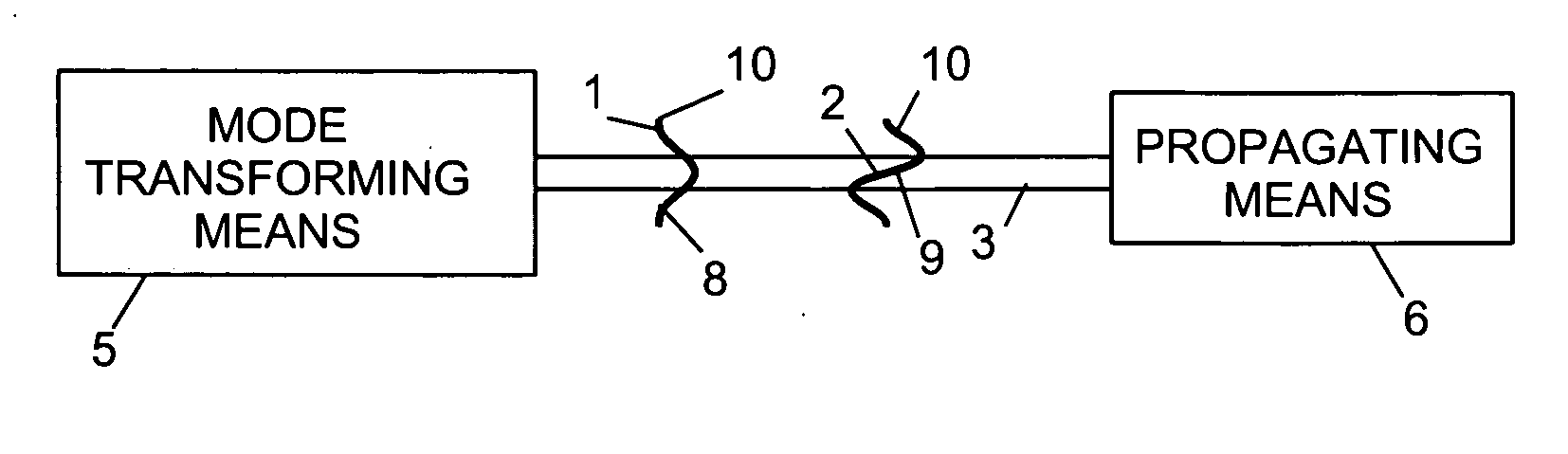
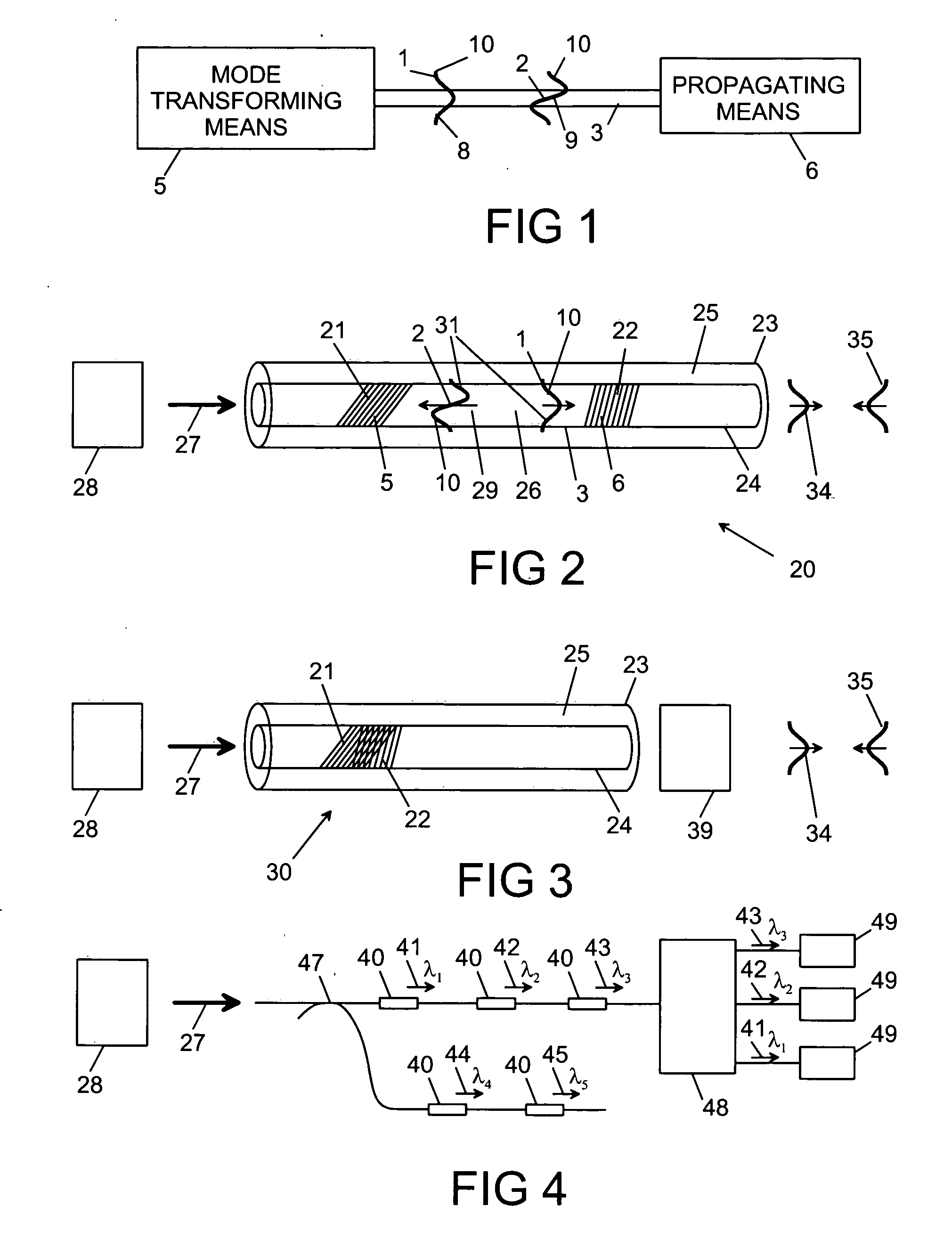
[0060] With reference to FIG. 1, there is provided apparatus for propagating optical radiation 10 in a first optical mode 1 having a first spatial mode shape 8, and a second optical mode 2 having a second spatial mode shape 9, which apparatus comprises an optical path 3, mode transforming means 5, and propagating means 6, wherein the mode transforming means 5 transforms at least a portion of the first optical mode 1 to the second optical mode 2, the propagating means 5 is configured such that in use at least some of the optical radiation 10 propagates along the optical path 3 more than once, and the apparatus is characterised in that the first spatial mode shape 8 is different from the second spatial mode shape 9.

[0061] There is shown in FIG. 2 apparatus in the form of a laser 20 in which the mode transforming means 5 is a first grating 21, and the propagating means 6 is a second grating 22. The first and second gratings 21, 22 are integral feedback means and mode transformers that...


PUM


Abstract

An apparatus for propagating optical radiation in a first optical mode having a first spatial mode shape, and a second optical mode having a second spatial mode shape. The first spatial mode shape is different from the second spatial mode shape. The apparatus includes an optical path and a mode transformer. The mode transformer transforms at least a portion of the first optical mode to the second optical mode. The apparatus further includes components for radiation propagation such that in use at least some of the optical radiation propagates along the optical path more than once.

Description

CROSS REFERENCE TO RELATED APPLICATIONS [0001] The present application claims priority under 35 U.S.C. 119 to United Kingdom (Great Britain) Patent Application Ser. No. GB0500277.9, filed in The United Kingdom on 7 Jan. 2005.FIELD OF INVENTION [0002] This invention relates to an apparatus for propagating optical radiation. The invention can take various forms, for example a passive cavity, a laser and a ring laser. The invention has application for sensing and communication systems. BACKGROUND TO THE INVENTION [0003] Fibre lasers can be configured as sensing elements. Examples are distributed feedback DFB fibre lasers which comprise a fibre Bragg grating written into a single mode optical fibre doped with a rare-earth dopant pumped by optical pump radiation. The laser emits light at a wavelength defined by the Bragg grating. The wavelength is modulated by a physical parameter such as acoustic pressure, and this modulation can be measured by analysing the light emitted by the laser u...

Claims


Application Information

Patent Timeline
Patent Type & Authority Applications(United States)
IPC IPC(8): G02B6/26H01S3/067
CPCH01S3/06729H01S3/06737H01S3/06791H01S3/06754H01S3/0675
Inventor HICKEY, LOUISE MARY BRENDANVARNHAM, MALCOLM PAULZERVAS, MIKHAIL NICKOIAOS
Owner HICKEY LOUISE MARY BRENDAN
Why Eureka
Try Eureka