
Firearm authorization system with piezo-electric disabler

a piezo-electric disabler and authorization system technology, applied in the field of firearm safety, can solve the problems of not being able to fire the firearm, the use of a piezo-electric-based enabler draws very little power, and the user cannot load the hammer in order to strike the firing pin, etc., to achieve the effect of reducing battery consumption, reducing power consumption, and reducing power consumption

Active Publication Date: 2006-11-02
FN HERSTAL
View PDF11 Cites 27 Cited by
  • Summary
  • Abstract
  • Description
  • Claims
  • Application Information

AI Technical Summary

Benefits of technology

[0008] The combination of circuit logic and the type of enabler is another important feature of the present invention. In addition to having authorization logic oriented to best suit the needs of law enforcement personnel, the logic also minimizes battery consumption. For example, the power-consuming authorization process is only done when the gun is out of the holster and the firearm is being held in such a way as to indicate that the user may fire it. There is also a “sleep mode” when the gun is out of the holster but not within the user's grasp. In this mode it draws very little power. In the holster it draws none. Only when the person grasping the gun is not authorized, which is likely a very small percentage of the time, does the system require power for the enabler. Furthermore, use of a piezo-electric-based enabler draws very little power compared to disablers bases on solenoids for example. Accordingly, in the case of battery failure, the firearm will fire because the system has been designed according to the police requirement to be “fail-fire”.

Problems solved by technology

If not authorized, the user will not be able to fire the firearm.
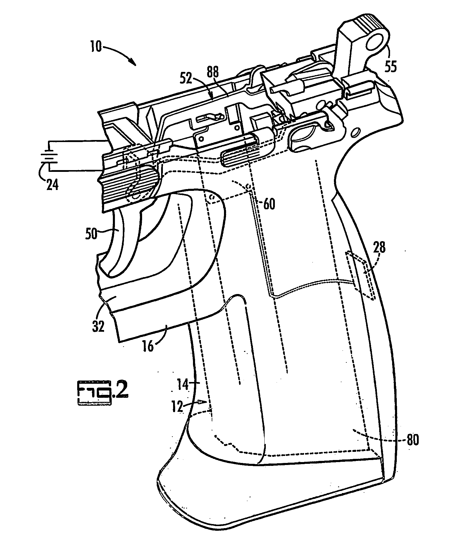
Specifically, a failure to authorize causes the disabler to cam the trigger bar clear of the hammer so the trigger bar cannot engage and thereby load the hammer.
As a consequence, the hammer cannot be loaded in order to strike the firing pin.
Furthermore, use of a piezo-electric-based enabler draws very little power compared to disablers bases on solenoids for example.

Method used


Image

  • Firearm authorization system with piezo-electric disabler
  • Firearm authorization system with piezo-electric disabler
  • Firearm authorization system with piezo-electric disabler

Examples


Embodiment Construction

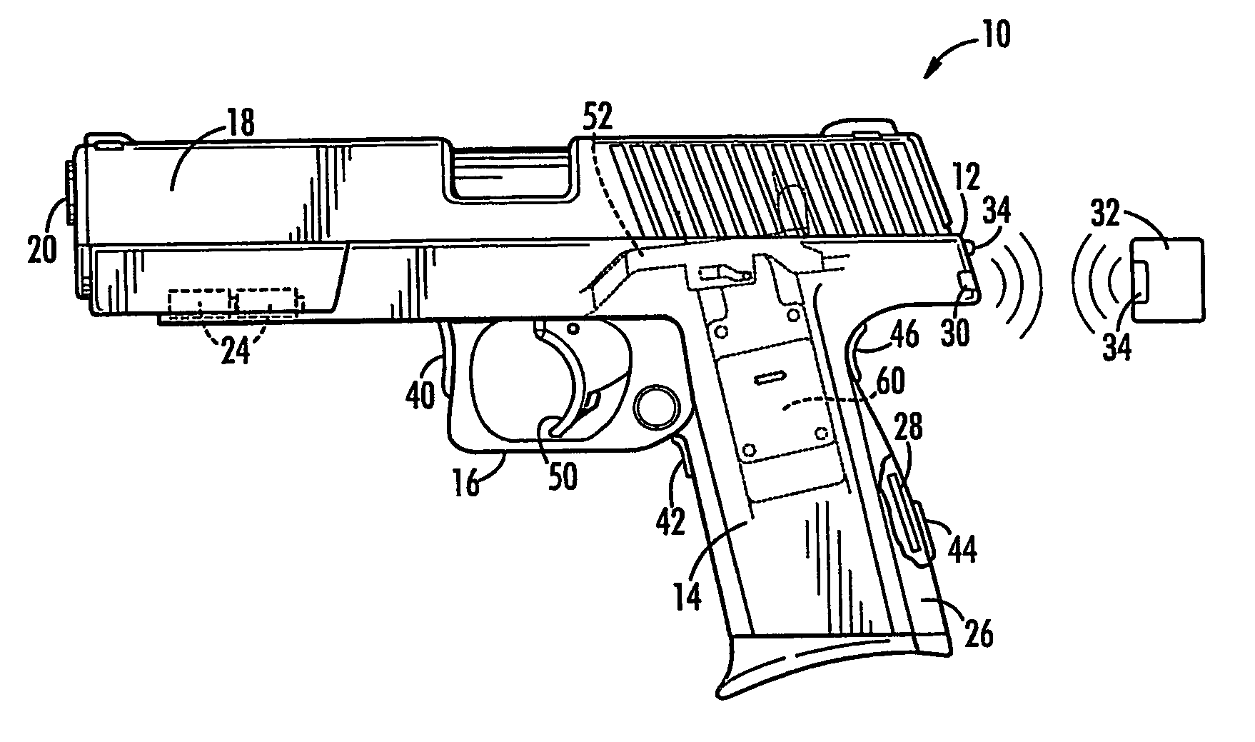
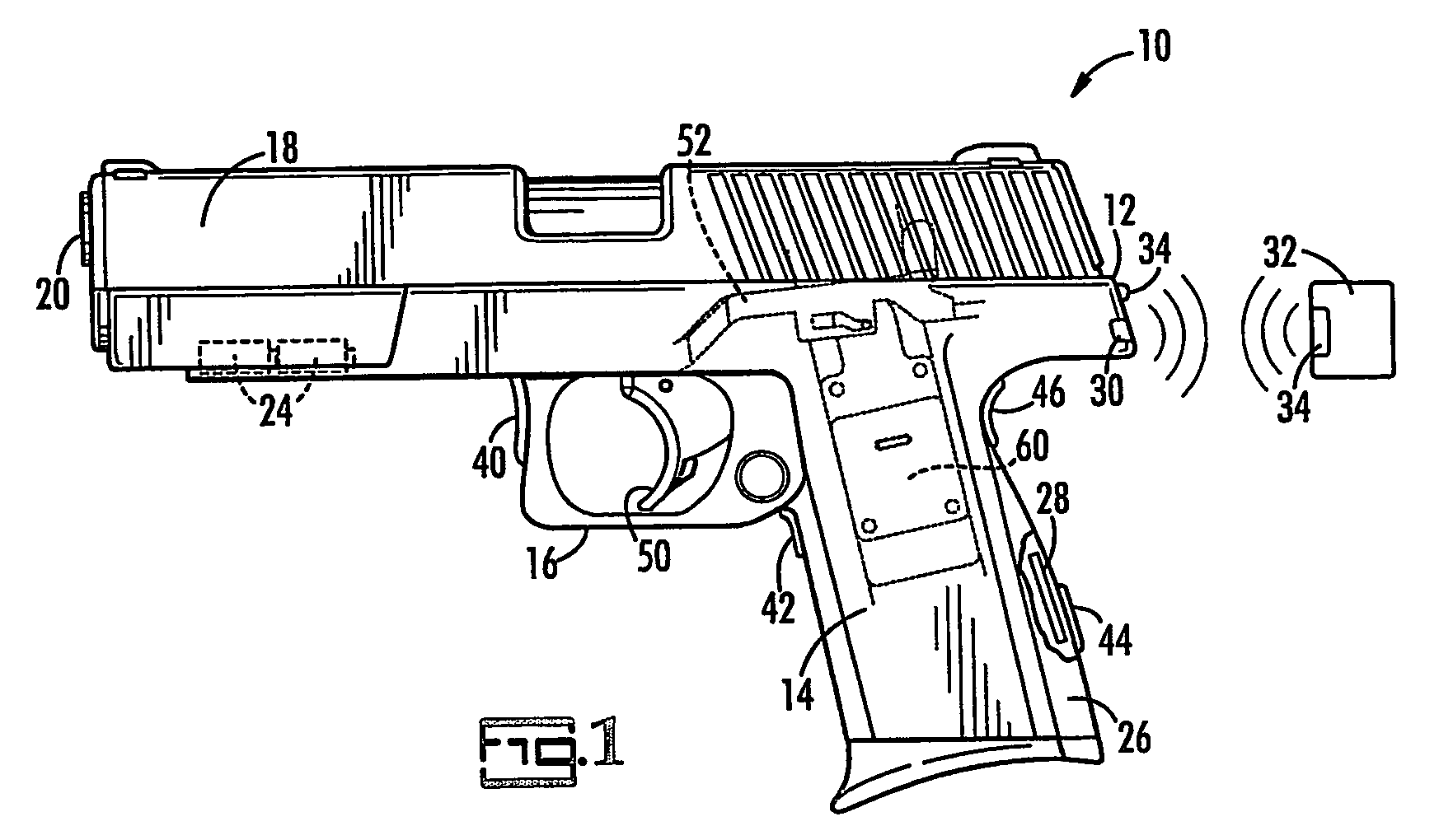
[0015] The present invention is a firearm with an authorization system. The authorization system will disable the firearm so that it will not fire if the user is an unauthorized user. Otherwise, the firearm will fire. The present invention includes a firearm, and an authorization device for emitting an authorizing signal to the firearm when queried by the firearm. The firearm includes a fire control system, a computer controller that communicates with the authorization device, and a piezo-electric-based disabler that responds to the computer controller.

[0016] Referring now to the figures, an embodiment of the present firearm 10 with the present authorization system is illustrated. In most respects, firearm 10 is a conventional firearm, here illustrated as a semi-automatic firearm. It has all of the components of a typical firearm, including, for example, a frame 12 with a handle 14 and trigger guard 16, a slide 18, and a barrel 20.

[0017] Firearm 10 may carry a power source such as...


PUM


Abstract

An authorization system for a firearm (10) includes an authorizing device (32) worn by the authorized user, and a firearm (10) with a fire control system, a computer controller (28), and a piezo-electric disabler (60). The computer controller (28) communicates with the authorizing device (32), and if no authorizing signal is received from the authorizing device, sends an electric output signal to the disabler (60) to prevent the fire control system from allowing the firearm to fire. The disabler, upon application of the electrical signal from the computer controller, cams the rearward moving trigger bar (52) of the fire control system clear of the hammer line (54) to disrupt the fire control system. Consequently, the firearm (10) will not fire.

Description

BACKGROUND OF THE INVENTION [0001] The present invention relates to firearm safety in general and to firearms with authorization systems in particular. [0002] There have been numerous improvements to firearm safety over the years. Historically, firearm safeties were of the type that, when the user wanted to fire the weapon, he or she moved a safety lever or catch from the “on” position to the “off”position. None of these safeties, however, questions the authority of the user who intends to fire the firearm. Any user may intentionally fire the firearm. [0003] More recently, firearms have been designed with authorization systems. These systems attempt to verify that the user is permitted to fire the firearm. An unauthorized user cannot fire the firearm equipped with an authorization system. Typically, these systems rely on some means of identification: the user enters a code on a keypad on the firearm or has a key that unlocks the firearm, or the firearm has the capability to read a p...

Claims


Application Information

Patent Timeline
IPC IPC(8): F41A17/00F41A17/06
CPCF41A17/063
Inventor SCHMITTER, EDWARD P.
Owner FN HERSTAL
Learn More