
Battery-powered, wireless gas sensing unit

a gas sensing unit and wireless technology, applied in the field of gas sensing, can solve the problems of limited portability of gas sensing units, difficulty in monitoring iaq in industrial factories or plants, and operator danger, and achieve the effect of saving battery, maximizing the life of the battery unit of the gas sensing unit in accordance with the present invention, and low demand

Inactive Publication Date: 2017-08-24
IQUNET BVBA
View PDF2 Cites 12 Cited by
  • Summary
  • Abstract
  • Description
  • Claims
  • Application Information

AI Technical Summary

Benefits of technology

The present invention is a gas sensing unit that maximizes the lifetime of its battery unit by measuring a first parameter with low impact on the battery life. The value of the first parameter can be measured frequently without draining the battery unit. Only when the value of the first parameter exceeds a predefined threshold, a gas concentration is measured using a second sensor. The gas concentration is only transmitted when it exceeds a predefined concentration threshold. This minimizes battery consumption and ensures that relevant gas concentrations are measured and transmitted. Overall, the gas sensing unit saves battery power and reduces battery consumption.

Problems solved by technology

Most gas sensing units present on the market, and especially CO2 sensors, are bulky and are electrically cabled to power lines.
The portability of such gas sensing units is then limited.
Additionally, monitoring the IAQ in an industrial factory or plant may be difficult and / or even dangerous for an operator.
For example, it may be dangerous to physically access the surroundings of a machine and / or it may be troublesome to suspend the normal operation of a machine in order to perform the measurement of a gas concentration.
Additionally, industrial factories or plants are usually wearisome environments for electronic components, making them subject to corrosion and subjecting them to electromagnetic interferences.
This requires the detector to be continuously powered and is therefore battery intensive, thereby reducing the battery lifetime.
Even though US2015 / 0077737A1 describes that the frequency at which the detector simultaneously collects the above measurements may decrease when a user is not present in an environment, there exists a risk that the batteries will frequently need changing, thereby resulting in frequent costs and requiring frequent interventions to change them.

Method used


Image

  • Battery-powered, wireless gas sensing unit
  • Battery-powered, wireless gas sensing unit
  • Battery-powered, wireless gas sensing unit

Examples


Embodiment Construction

)

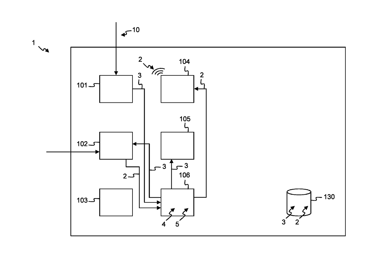
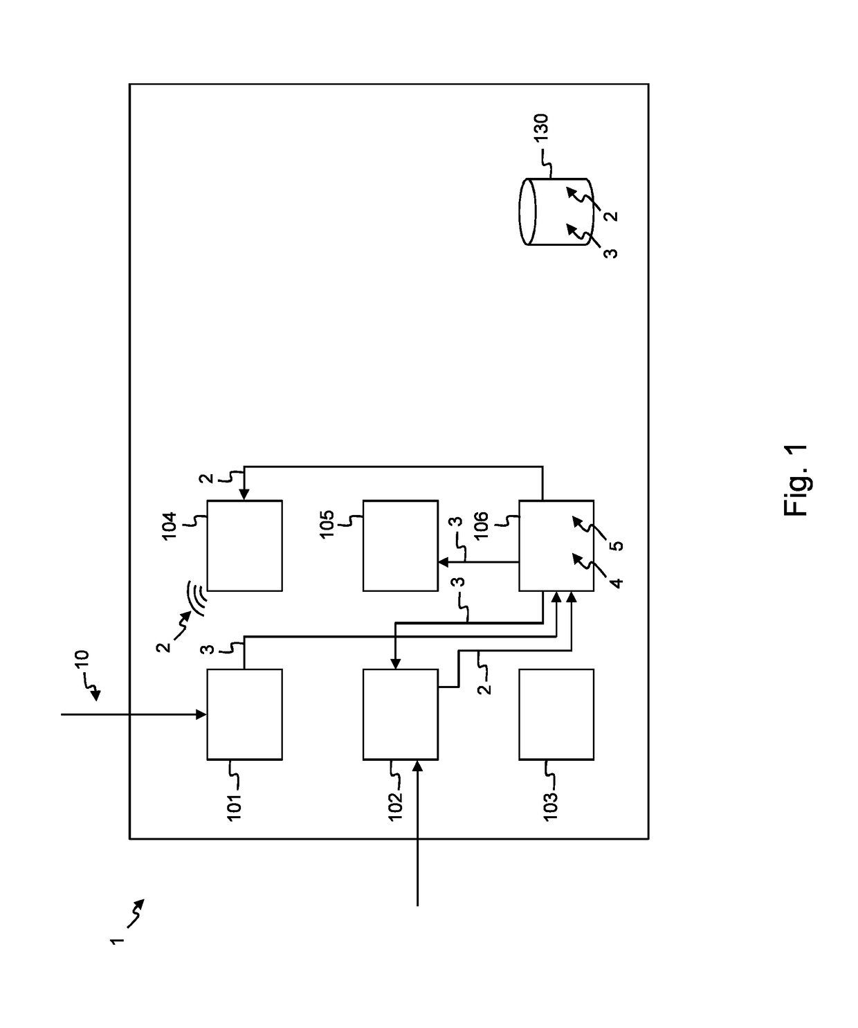
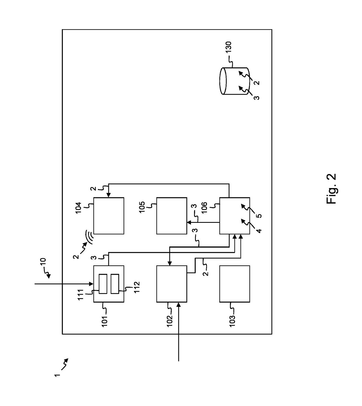
[0061]According to an embodiment shown in FIG. 1, a battery-operated, wireless gas sensing unit 1 comprises a first sensor 101, a second sensor 102, a battery unit 103, a wireless transmitter 104, a processor 105, a controller 106 and a memory 130. Crossing lines in FIG. 1 are not to be interpreted as connections. The first sensor 101 frequently measures a value 3 of a first parameter 10. For example, the first sensor 101 measures a value 3 of a first parameter 10 periodically. The first sensor 101 can for example measure a value 3 of a first parameter 10 every 30 seconds, every minute, every 2 minutes, every 5 minutes, every 10 minutes, every 30 minutes, every hour, every 12 hours, or every 24 hours, etc. According to an alternative embodiment, the first sensor 101 frequently measures a value 3 of a first parameter 10. For example, the first sensor 101 measures a value 3 of a first parameter 10 several times per minute, or several times per hour, or several times per day, etc. A v...


PUM

PropertyMeasurementUnit
temperatureaaaaaaaaaa

Abstract

A battery-powered, wireless gas sensing unit for measuring a gas concentration, the gas sensing unit comprising a first sensor, a second sensor, a battery unit, a wireless transmitter, a processor and a controller. The first sensor is adapted to frequently measure a value of a first parameter. The second sensor and the processor are controlled to measure the gas concentration only when the value of the first parameter or variation of the value of the first parameter exceeds a predefined first parameter threshold. The wireless transmitter is controlled to transmit the gas concentration only when the gas concentration exceeds a predefined concentration threshold.

Description

FIELD OF THE INVENTION[0001]The present invention generally relates to gas sensing and particularly to gas sensing units forming parts of the Internet of Things and adapted to measure gas concentrations in atmospheres.[0002]Indoor air quality, also referred to as IAQ, is a term which refers to the air quality within and around buildings and structures, especially as it relates to the health and comfort of building occupants. IAQ can be affected by constituents of air, such as gases, for example carbon monoxide, carbon dioxide or CO2, radon, volatile organic compounds or VOCs, etc., which can induce adverse health conditions. Monitoring the IAQ in homes and buildings comprises measuring gas concentrations in their atmospheres. For example, high CO2 concentrations can be found near vehicle traffic areas, industry and sources of combustion. Fluctuations in air constituents in these atmospheres may indicate events which may be important to relay to homes and buildings occupants.[0003]Th...

Claims


Application Information

Patent Timeline
Patent Type & Authority Applications(United States)
IPC IPC(8): G01N33/00H04L1/00
CPCG01N33/0031G01N33/0062H04L63/0428G01N33/004H04L1/0041G01N33/0047G01N33/0065F24F2110/70Y02B30/70
Inventor VEREECKEN, WIMVAN DEN BRANDEN, DIRK
Owner IQUNET BVBA
Learn More