Method and apparatus for the conversion of beverage vending machine

a beverage vending machine and beverage technology, applied in the field of beverage vending machine conversion, can solve the problems of unfavorable recycling and scrapping of older machines, and the cost of recycling and scrapping such machines is not without cost, so as to save the vendor

Inactive Publication Date: 2005-03-29
GALLO RALPH
View PDF5 Cites 5 Cited by
  • Summary
  • Abstract
  • Description
  • Claims
  • Application Information

AI Technical Summary

Benefits of technology

One aspect of the invention deals with a basic problem in the refurbishing, recycling and disposal of vending equipment—the need to frequently update or replace such equipment when product packaging is changed or modified (e.g., size or shape of packaging such as a change from 12-ounce cans to 16- or 20-ounce bottles). This aspect is further based on the discovery of a technique that alleviates this problem. The technique utilizes the essential components of an existing machine, modifying only a few parts, so as to allow a beverage vending machine to be changed from can to bottle vending with only a reasonable amount of effort. In this way, vendors are able to have their machines refurbished rather than having to replace the old machines with costly new machines.
The techniques and aspects of the invention described herein are advantageous because they are both straightforward and inexpensive compared to other approaches, and make it unnecessary to completely scrap older yet functional vending machines. As a result of the invention, conventional can vending machines may be easily modified to allow the machines to vend newer, larger bottles—thereby saving the vendor from the expense of having to replace can vending machines.

Problems solved by technology

Moreover, the replacement of the older style machines, while still functional, results in numerous older machines needing to be recycled and scrapped.
The recycling and scrapping of such machines is also not without cost as there are components (e.g., refrigerants) that must be properly recovered and disposed of before the machines can be scrapped for the metal.

Method used


Image

  • Method and apparatus for the conversion of beverage vending machine
  • Method and apparatus for the conversion of beverage vending machine
  • Method and apparatus for the conversion of beverage vending machine

Examples


Embodiment Construction

For a general understanding of the present invention, reference is made to the drawings. In the drawings, like reference numerals have been used throughout to designate identical elements,

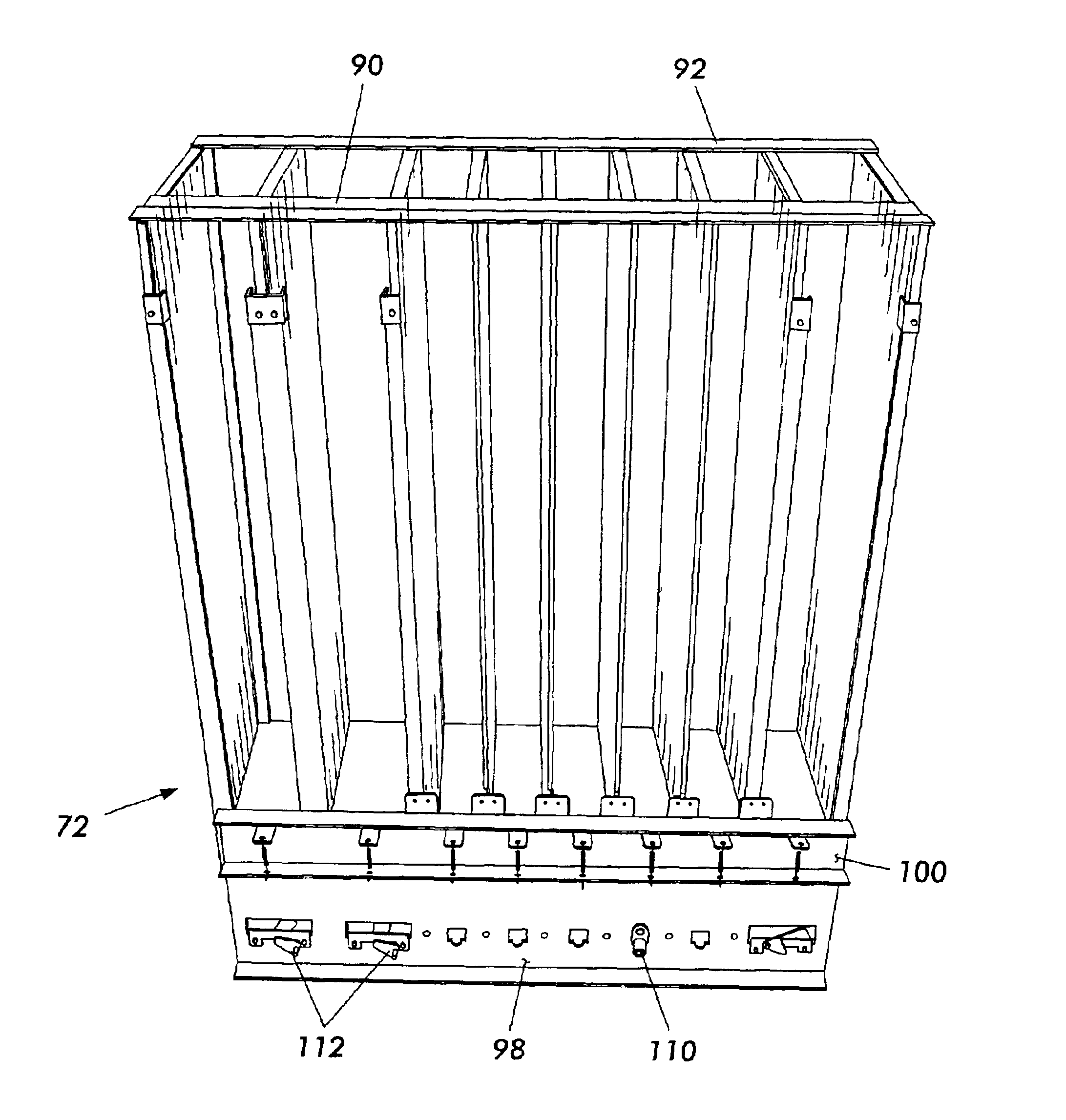
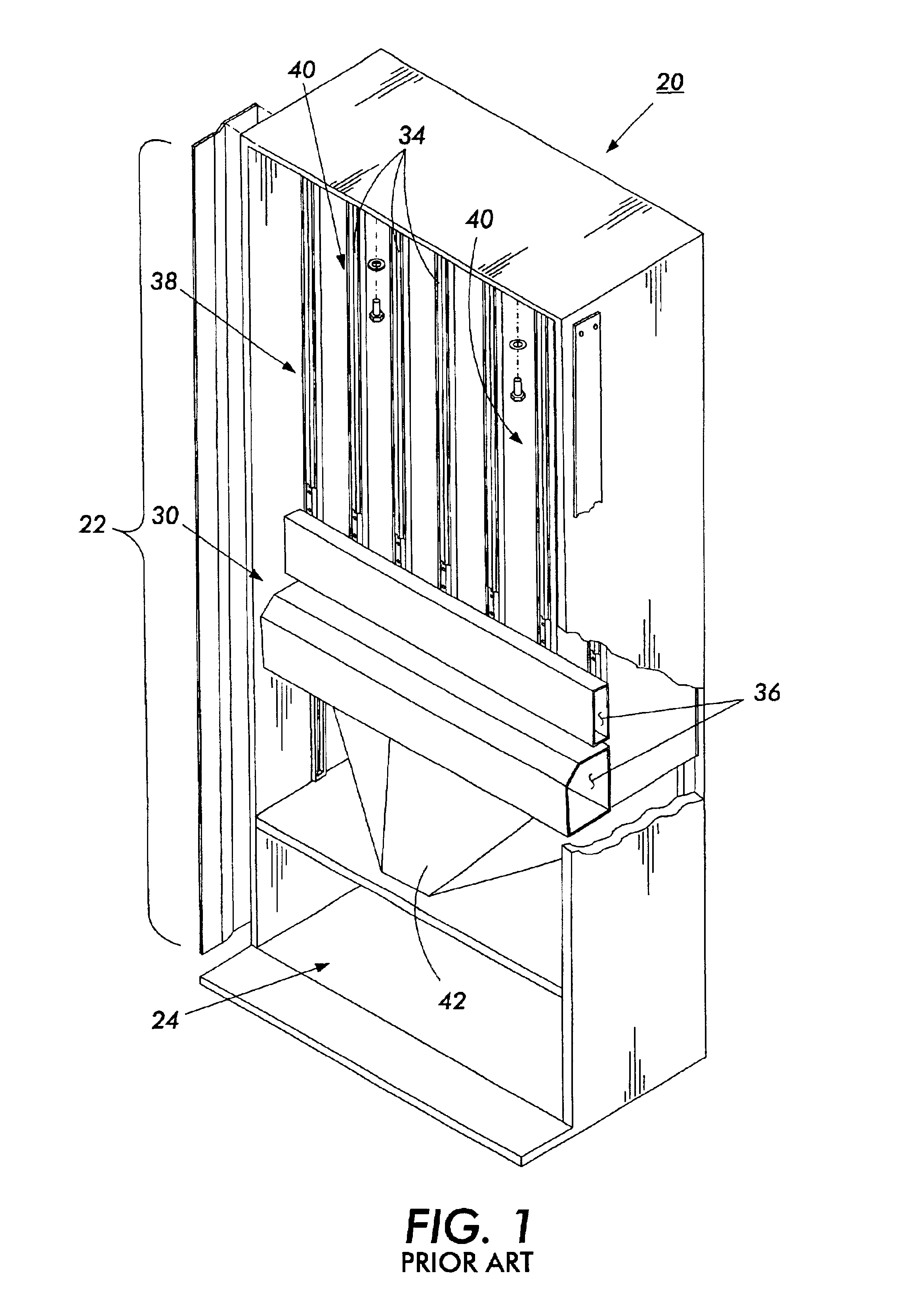
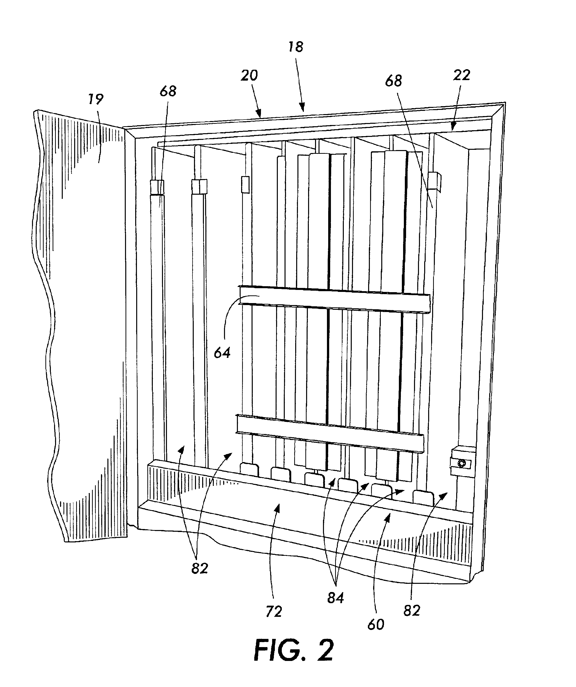
In describing the present invention, the following term(s) have been used to describe the vending machines. An “upper interior cabinet” is an open region, generally including the upper portion of the vending machine, where apparatus to store and dispense goods are located. In beverage vending machines, the upper interior cabinet is often refrigerated. A “vend mechanism” or “vend mechanism assembly” is an assembly, generally inserted or located within the upper interior cabinet, that controls the advancement and dispensing of goods from the vending machine. In a beverage vending machine, the vend mechanism generally includes a rack (bottles or cans) or similar storage mechanism for storing the beverage containers, dispensing devices to control the dispensing of containers into a chute located at the...


PUM


Abstract

The present invention is a method and apparatus a method and apparatus for the refurbishment of a beverage vending machine to enable a can vending machine to be reconfigured for the dispensing of bottles. In particular, the apparatus and process are directed to the modification of certain components of a can vending machine to enable it to be utilized for dispensing of newer, 16- or 20-ounce beverage bottles. The modification includes a change in the spacing and configuration of the container storage rack and the modification of dispensing mechanisms to allow a can-type system to dispense bottles and thereby avoid the need to completely replace the vending machine.

Description

This invention relates generally to modification of a vending machine, and more particularly to the conversion of a traditional 12-ounce can vending machine to enable the machine to be used for the vending of 16- or 20-ounce bottles.COPYRIGHT NOTICEA portion of the disclosure of this patent document contains material which is subject to copyright protection. The copyright owner has no objection to the facsimile reproduction by anyone of the patent document or the patent disclosure, as it appears in the Patent and Trademark Office patent file or records, but otherwise reserves all copyright rights whatsoever.BACKGROUND AND SUMMARY OF THE INVENTIONThe present invention is directed to a method and an associated apparatus that enables the conversion or reconditioning of an existing vending machine to handle items contained in alternatively sized packages. More specifically, the invention relates to the conversion of a can-type beverage vending machine to enable the machine to dispense n...

Claims


Application Information

Patent Timeline
Patent Type & Authority Patents(United States)
IPC IPC(8): G07F11/00G07F11/04
CPCG07F11/04
Inventor GALLO, RALPH
Owner GALLO RALPH
Why Eureka
Try Eureka