Electromagnetic induction welding of fluid distribution systems

a technology of fluid distribution system and induction welding, which is applied in the direction of pipe couplings, couplings, other domestic objects, etc., can solve the problems of undesirable internal plastic deformation of pipe ends, disruption of fluid flow, and induction welding operation introducing undesirable uncertainty, so as to achieve precise induction welding operation, save dissolvable material, and high melting temperature

Active Publication Date: 2017-01-19
HULIOT (A C S) LTD
View PDF4 Cites 6 Cited by
  • Summary
  • Abstract
  • Description
  • Claims
  • Application Information

AI Technical Summary

Benefits of technology

[0011]Yet another aspect of the present invention is directed towards induction weldable pipe connectors with integral solder flow barrier for use in assembling fluid distribution systems. The integral solder flow barriers are mounted inside induction weldable pipe connectors and designed to control the inward radial flow of melted internal thermoplastic solder lining on application of induction energy thereby affording a more precise induction welding operation. Induction weldable pipe connectors with integral solder flow barriers according to the present invention can be tailored for assembling either thermoplastic pipes or plastic pipes having inherent mechanical rigidity either by virtue of being made of thermoset plastic materials or having an aluminium core layer.
[0012]In the former case of thermoplastic pipes, an integral solder flow barrier is additionally intended to provide structural rigidity to pipe ends undergoing induction welding and therefore it is necessarily longer than its associated induction weldable pipe connector to extend to unheated lengths of the pipe ends being induction welded together. Integral solder flow barriers for use with thermoplastic pipes can be made of a thermoset plastic material having a higher melting temperature than an internal thermoplastic solder lining such that it is not affected during an induction welding operation. Alternatively, integral solder flow barriers can be made from a dissolvable material intended to be dissolved by a fluid flowing through a fluid distribution system. Suitable dissolvable materials include common salt.
[0013]In the latter case of plastic pipes having inherent mechanical rigidity, an integral solder flow barrier can be considerably shorter than its associated induction weldable pipe connector, thereby saving dissolvable material in the case of a dissolvable integral solder flow barrier. Flow control over melting internal thermoplastic solder lining is particularly important in the case of multi-layer pipes with aluminium core layers to ensure that the melting internal thermoplastic solder lining material absolutely seals the annular aluminium core end faces to preclude their oxidation which can lead to pipe failure.

Problems solved by technology

Induction welding of an induction weldable pipe connector and a thermoplastic pipe can transfer inadvertently excessive heat energy to a pipe end thereby introducing an undesirable measure of uncertainty in an induction welding operation.
Such inadvertent excessive heat energy can lead to undesirable internal plastic deformations of a pipe end which may be undetectable to construction personnel assembling a fluid distribution system.
Such internal plastic deformations can cause disruptions in fluid flow through a fluid distribution system at an induction weldable pipe connector.
“Press fit” installation fittings are relatively expensive and construction personnel require a considerable range of “press fit” installation fittings to complete a multi-layer pipe fluid distribution system.

Method used


Image

  • Electromagnetic induction welding of fluid distribution systems
  • Electromagnetic induction welding of fluid distribution systems
  • Electromagnetic induction welding of fluid distribution systems

Examples


Embodiment Construction

Section 1: WO 2012 / 137197 Electromagnetic Induction Welding of Plastic Pipe Distribution Systems

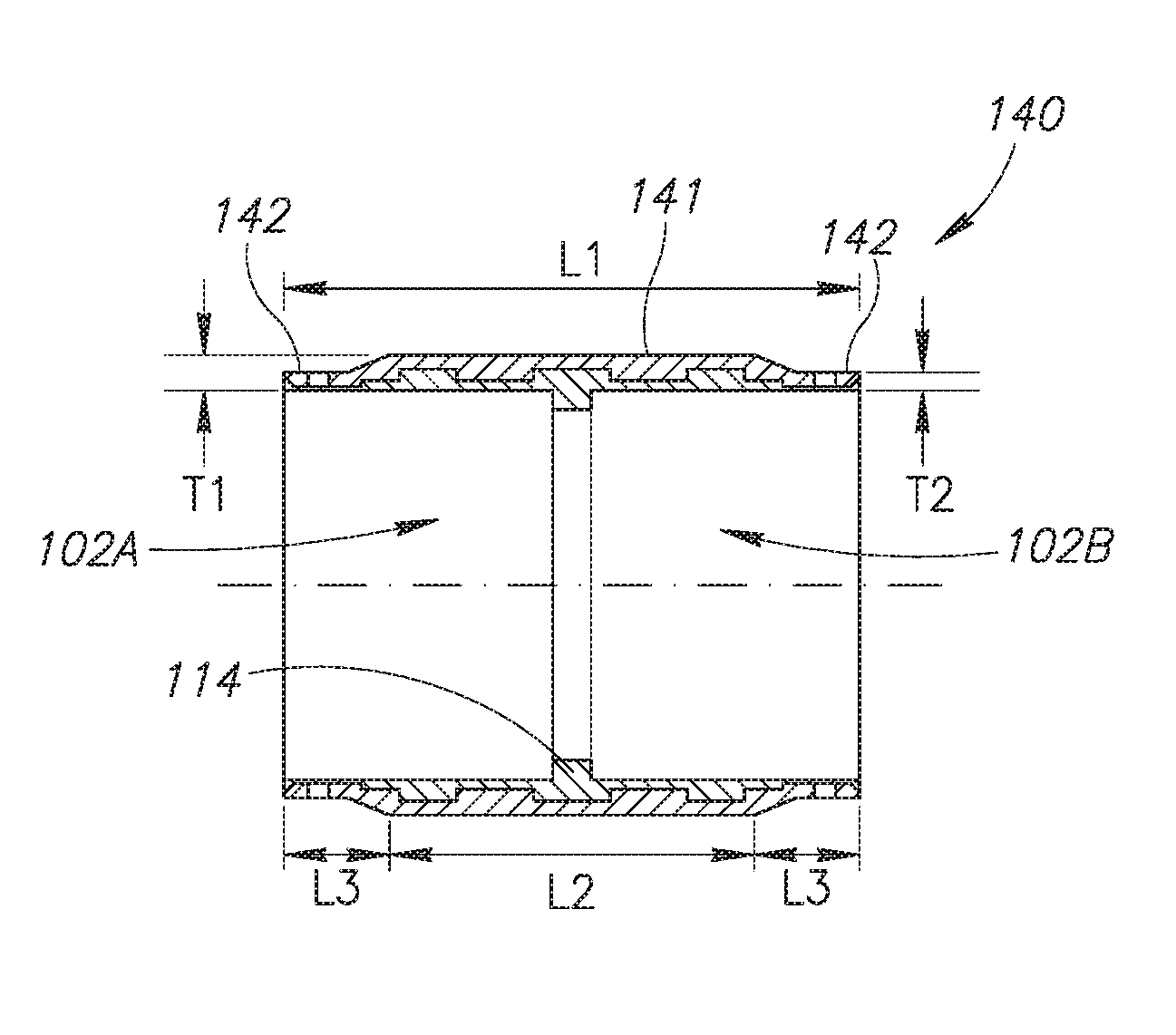
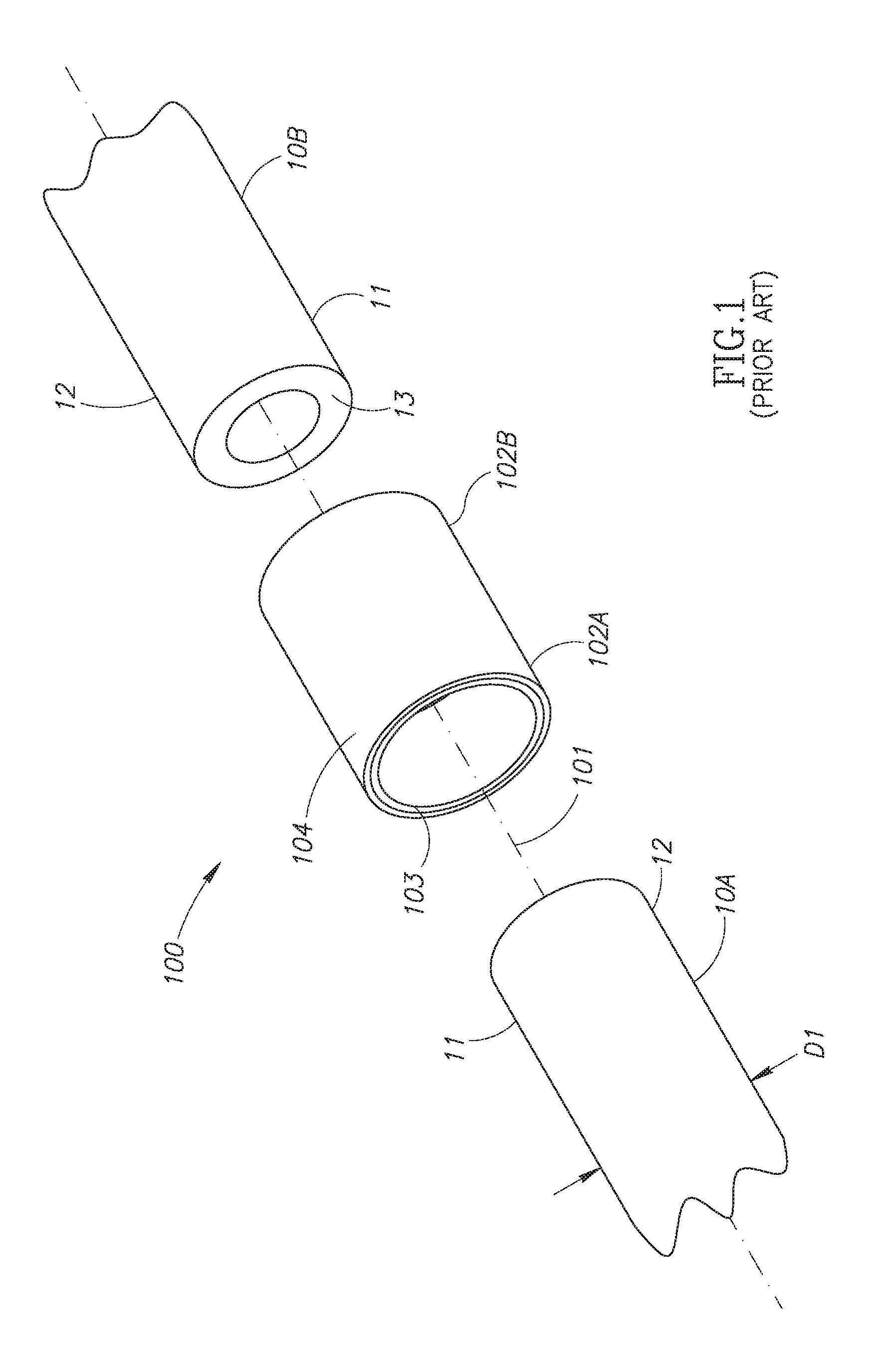
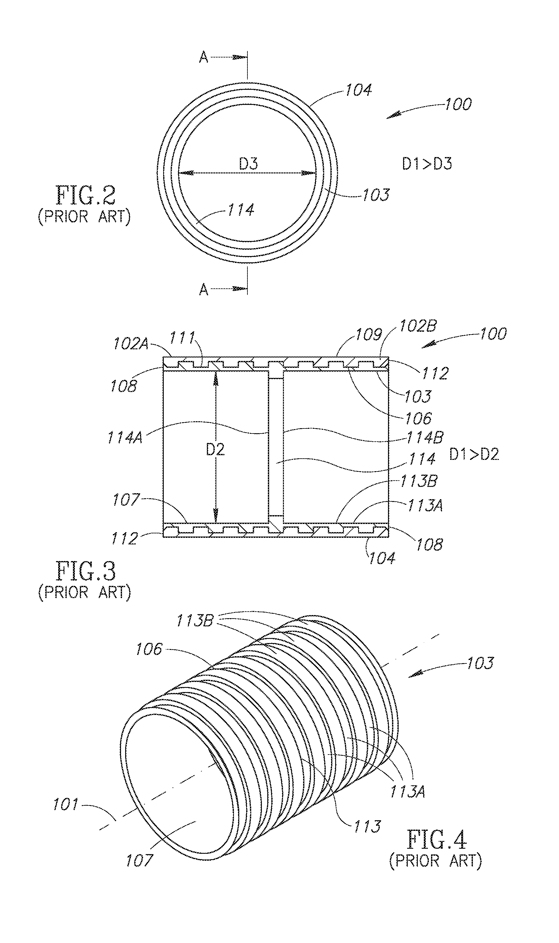
[0046]Commonly owned WO 2012 / 137197 FIGS. 1 to 4 show an induction weldable pipe connector 100 for electromagnetic induction welding to a pair of same diameter thermoplastic pipes 10. The thermoplastic pipes 10 have an external diameter D1 typically in the range of from 10 mm to 30 mm. The thermoplastic pipes 10 have pipe ends 11. The pipe ends 11 have peripheral external pipe end surfaces 12 and exposed annular pipe end faces 13.

[0047]The induction weldable pipe connector 100 has a longitudinal pipe connector axis 101 and includes two opposite induction weldable pipe sockets 102A and 102B each intended for forced sliding insertion of a pipe end 11 thereinto. The induction weldable pipe connector 100 has a two ply construction including an internal thermoplastic solder lining 103 and a solid ferromagnetic metal susceptor sleeve 104 entirely peripherally enveloping the internal thermoplast...


PUM

PropertyMeasurementUnit
acute angleaaaaaaaaaa
included acute angleaaaaaaaaaa

Abstract

Installation fittings for use with induction weldable pipe connectors for assembling multi-layer pipe fluid distribution systems. Induction welding pipe connectors including a major central pipe connector section and a minor lateral pipe connector section pair having reduced thickness relative to the major central pipe connector section. Induction welding pipe connectors with 5 integral solder flow barrier for assembling fluid distribution systems. Electromagnetic induction coil reverse action pliers for use with induction weldable pipe connectors for assembling fluid distribution systems.

Description

FIELD OF THE INVENTION[0001]The invention relates to electromagnetic induction welding of fluid distribution systems for the transport of fluids in residential, commercial and industrial plumbing systems.BACKGROUND OF THE INVENTION[0002]Commonly owned WIPO International Publication No. WO 2012 / 137197 entitled Electromagnetic Induction Welding of Plastic Pipe Distribution Systems discloses induction weldable pipe connectors and electromagnetic induction coil assemblies for use in clamping the induction weldable pipe connector on plastic pipes. The plastic pipes can be made from thermoplastics including inter alia PVC, PP, PP-R, HDPE and the like, and thermosetting plastics including inter alia PEX, and the like. The plastic pipes can have can be fabricated from a single plastic material throughout or alternatively have a multi-layer composition.[0003]The induction weldable pipe connectors each have at least one induction weldable pipe socket. Each induction weldable pipe socket inclu...

Claims


Application Information

Patent Timeline
Patent Type & Authority Applications(United States)
IPC IPC(8): B29C65/14F16L9/147F16L47/02B29C65/00
CPCB29C65/148B29C66/522B29C66/861B29C66/81262F16L2201/10F16L47/02B29K2101/12B29L2023/22F16L9/147B29C65/78B29C65/3656B29C65/3668B29C65/368B29C66/1222B29C66/1224B29C66/1226B29C66/12441B29C66/12469B29C66/3242B29C66/3472B29C66/5221B29C66/52241B29C66/52292B29C66/63B29C66/636B29C66/72321B29C66/73116B29C66/73921B29C66/81423B29C66/83241B29C66/8614B29C66/972B29K2705/02B29C65/7817B29C66/52298B29C66/52291B29C66/8748B29C66/9672B29C66/9674B29K2995/0008B29C66/71B29C66/8221B29C66/52296B29C66/7392B29C66/7394B29K2023/065B29K2027/06B29K2023/12B29K2023/0691
Inventor HOOBERMAN, GIDEONSTEINER, PAULYOGEV, ILAN
Owner HULIOT (A C S) LTD
Why Eureka
Try Eureka