Convertible fly rod

Inactive Publication Date: 2006-11-02
HALL ROGER C
View PDF20 Cites 2 Cited by
  • Summary
  • Abstract
  • Description
  • Claims
  • Application Information

AI Technical Summary

Benefits of technology

[0019] The present invention answers the aforementioned needs by providing a multi-section fly rod that is convertible quickly and easily between two configurations.
[0021] In one embodiment of such a convertible rod a rear hand grip is fastened removably to a rear portion of a reel seat by a joint which can easily be disconnected.

Problems solved by technology

Lacking such a space, as where an angler must remain close to a steep or tree-covered bank while casting across a wide expanse of water, another type of cast, such as a roll cast, might be used, but such other casting techniques are generally less efficient than an overhead cast in reaching long distances.
A shortcoming of such a casting technique, however, is that it requires a very long fly rod, which is heavier than a conventional rod used with one hand.
Because of their larger size, Spey fly rods are significantly more expensive than a conventional fly rod intended for use in one-handed casting techniques.
A Spey rod is infrequently needed, and is often too large to be used well in small streams.
Many anglers are therefore reluctant or unable to justify the greater cost of a Spey fly rod that is useful only on relatively infrequent occasions.
The prior art, however, does not adequately address the issues mentioned above.

Method used


Image

  • Convertible fly rod
  • Convertible fly rod
  • Convertible fly rod

Examples


Embodiment Construction

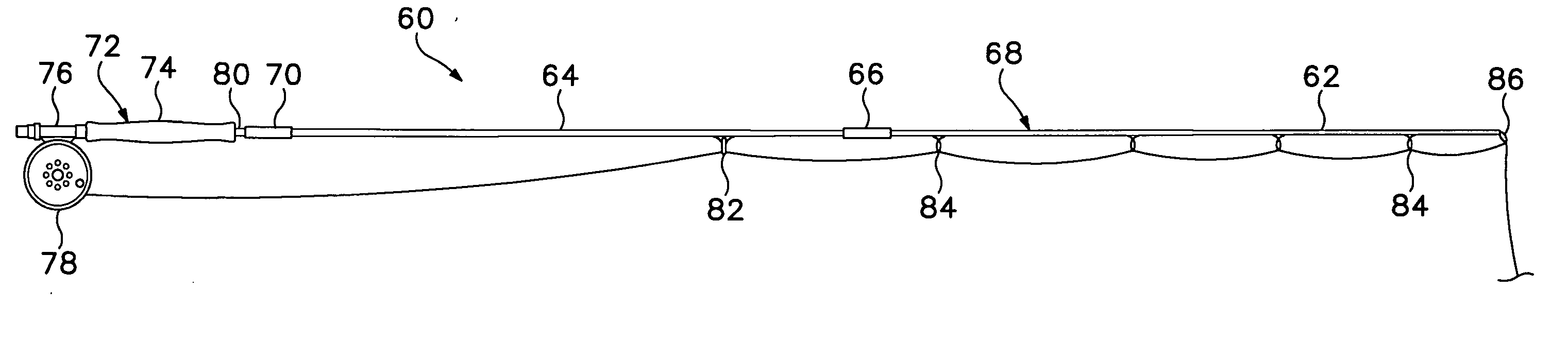
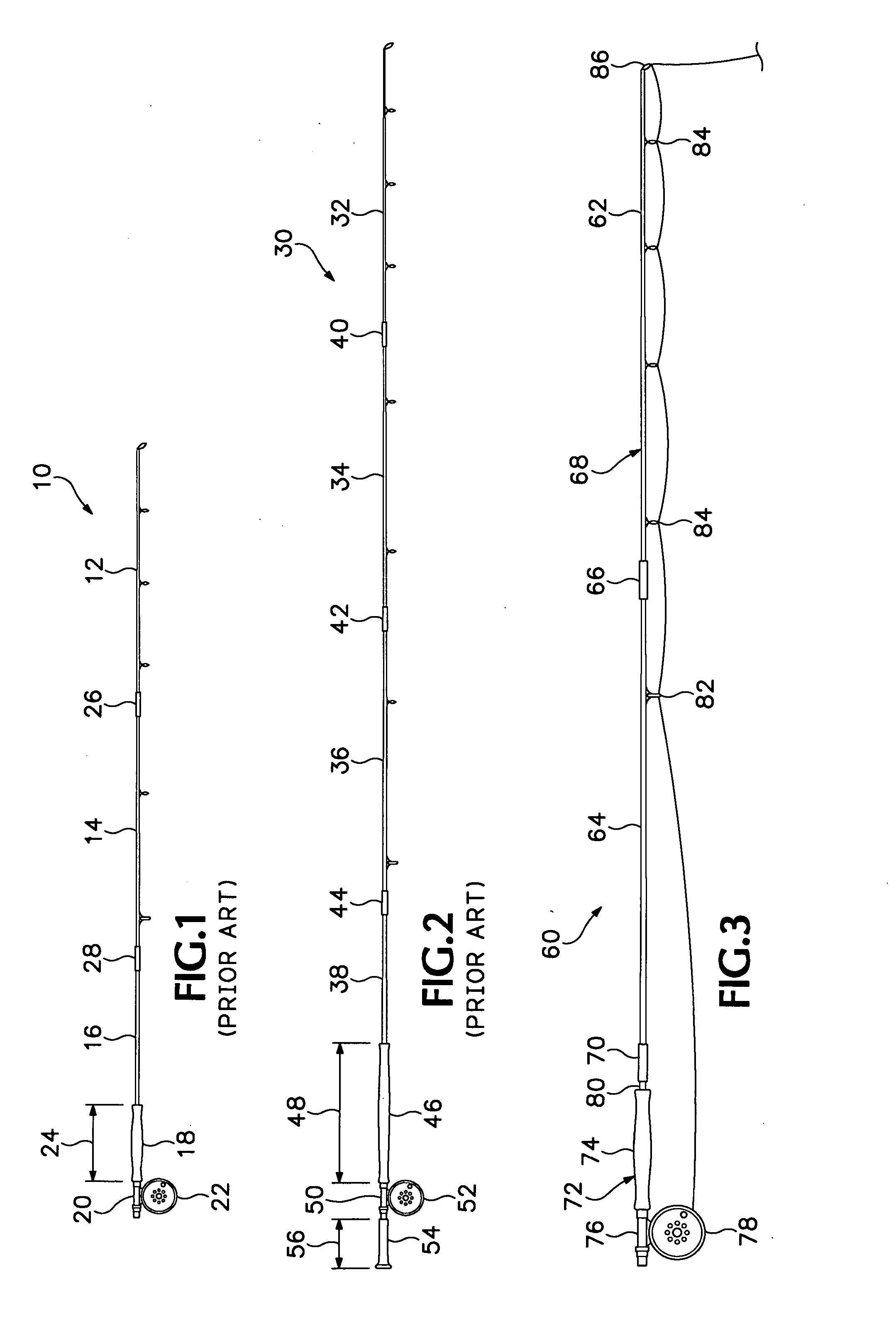
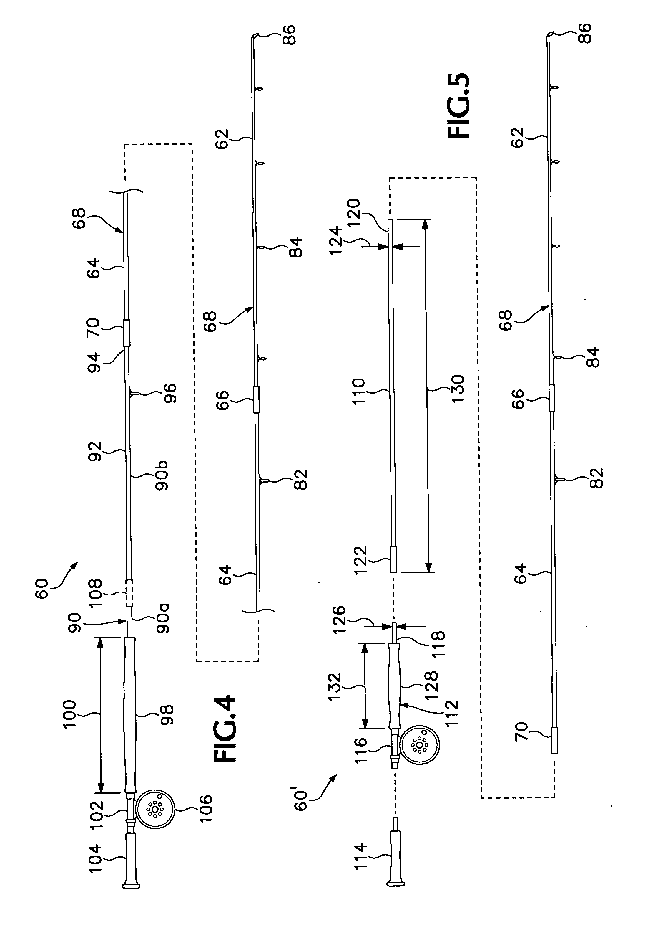
[0029] Referring now to FIGS. 3 and 4 of the drawings which form a part of the disclosure herein, a convertible rod 60 is shown in FIG. 3 in a first configuration suitable for use as a conventional fly rod to be held in one hand during casting, similar to the fly rod 10 described previously. A tip section 62 and an intermediate section 64, interconnected separably with each other by a conventional rod joint 66, together constitute a forward rod portion 68 of the rod 60. A rear connecting member 70, which may be one of the mating parts of a conventional rod joint, is located at the rear end of the forward rod portion 68. The forward rod portion 68 may instead be divided into a larger number of shorter sections, and thus may have one or two additional intermediate sections interconnected by rod joints, if it is desired for the convertible rod 60 to form a smaller package for greater convenience in carrying it disassembled.

[0030] A short rear end portion 72 includes a grip 74 generall...


PUM


Abstract

A flycasting rod that is convertible between a first configuration suitable for use while holding the rod in only one hand while casting flies, and a second configuration in which the rod includes two separate hand grips and an extension of the shaft of the rod, that is suitable for holding the rod with both hands and casting flies using the Spey techniques.

Description

BACKGROUND OF THE INVENTION [0001] The present invention relates to fishing rods, and in particular relates to a flycasting rod convertible between two different configurations for different methods of flycasting. [0002] In fly fishing a long, flexible, yet moderately stiff, tapered rod is used, together with a line that is heavy enough so that when the line is extended from the tip of the rod its weight can be applied to bend the rod in the process of casting a fly attached to the outer end of the line. By moving the rod, the line can be placed into motion, so that when the rod is stopped the line, continuing to move, flexes the tip of the rod. Thereafter, release of the potential energy stored in the bent rod accelerates the line in a different direction, together with a leader and a fly attached to the outer end of the leader. Further movement of the rod by a skilled caster can throw the line far enough to place the fly in a desired target location as far as 30 yards away. [0003]...

Claims


Application Information

Patent Timeline
IPC IPC(8): A01K87/00
CPCA01K87/02A01K87/00
Inventor HALL, ROGER C.
Owner HALL ROGER C
Why Eureka
Try Eureka