Electromagnetic door actuator system and method

a technology of electronic magnetic actuator and actuator, which is applied in the direction of door/window fitting, power supply, construction, etc., can solve the problems of difficulty for a child or an elderly or disabled person to open the door, the door actuator device has several known devices, and the speed of closur

Inactive Publication Date: 2006-11-02
MCKINNEY DAVID RUSSELL
View PDF9 Cites 157 Cited by
  • Summary
  • Abstract
  • Description
  • Claims
  • Application Information

AI Technical Summary

Benefits of technology

[0009] It has been recognized that it would be advantageous to develop a door actuator that is not bulky and obtrusive.

Problems solved by technology

However, the device also provides resistance to closure, thus damping and controlling the speed of closure, particularly near the end of the closing motion.
Unfortunately, known door actuator devices have several negative aspects.
Passive door actuators impose significant resistance to opening a door, which can make it difficult for a child or an elderly or disabled person to open the door.
This can be very inconvenient in many circumstances.
Additionally, passive door actuator devices tend to be bulky and unsightly, and if they malfunction, can cause a door to rapidly slam, which can be dangerous.
Power door actuators also tend to be bulky and unsightly, usually involving a large motor device located atop the door.
Additionally, These devices are also somewhat noisy, and of course their mechanical parts are subject to wear.
Furthermore, electric door actuators are not naturally configured to provide electronic output indicating the status of the door—whether closed or open, and how much.

Method used


Image

  • Electromagnetic door actuator system and method
  • Electromagnetic door actuator system and method
  • Electromagnetic door actuator system and method

Examples


Embodiment Construction

[0039] Reference will now be made to the exemplary embodiments illustrated in the drawings, and specific language will be used herein to describe the same. It will nevertheless be understood that no limitation of the scope of the invention is thereby intended. Alterations and further modifications of the inventive features illustrated herein, and additional applications of the principles of the inventions as illustrated herein, which would occur to one skilled in the relevant art and having possession of this disclosure, are to be considered within the scope of the invention.

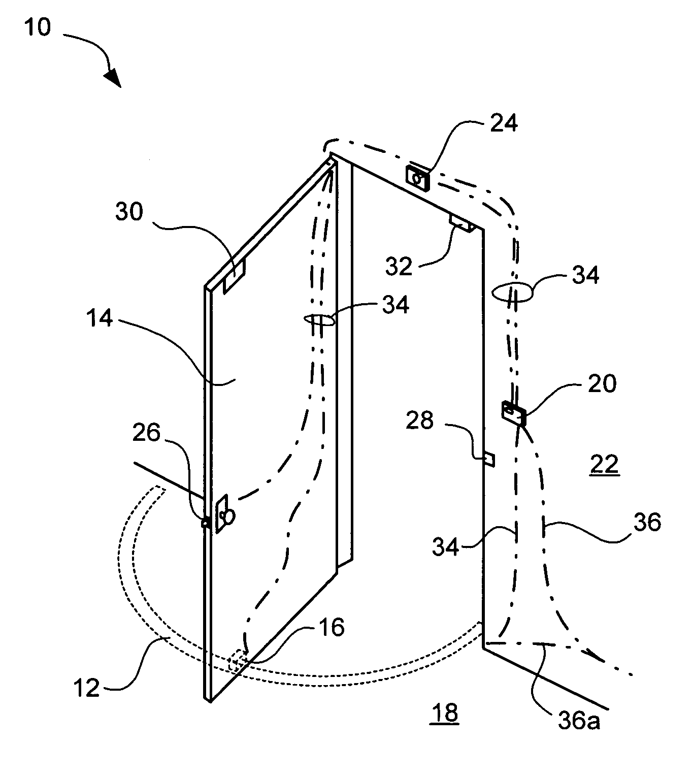
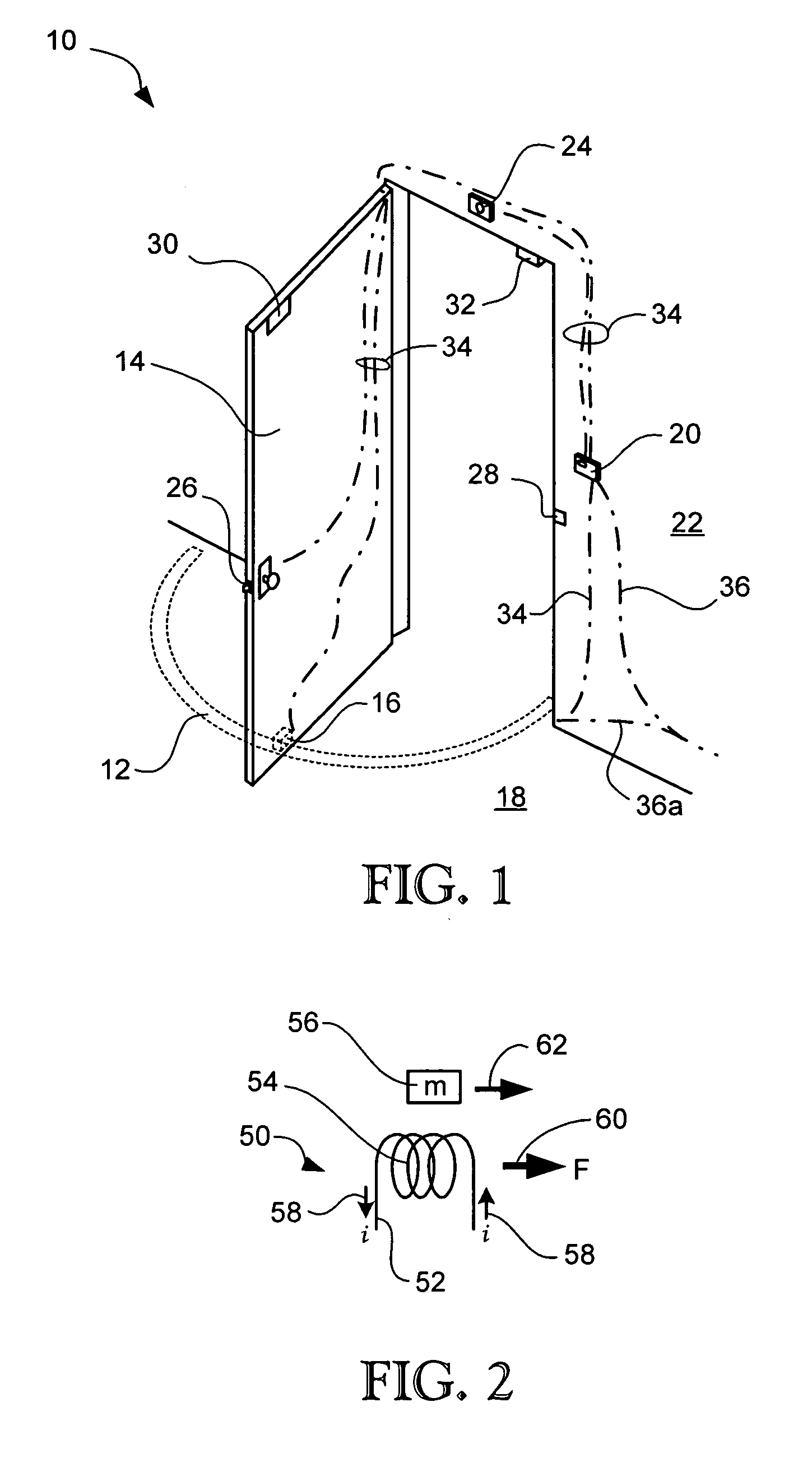
[0040] Shown in FIG. 1 is one embodiment of an electromagnetic door actuator system 10 in accordance with the present invention. The door actuator system generally comprises an elongate stator or static element 12 disposed adjacent to the path of motion of a door 14, and a dynamic element 16 attached to the door itself. In the embodiment shown in FIG. 1, the stator element is disposed upon or embedded within th...


PUM


Abstract

A door actuator system includes a linear motor, electromagnetically coupled between a moveable door and an adjacent non-moving structure, and a controller, interconnected to the linear motor, configured to power the linear motor to cause motion of the door, and to detect motion of the door from induced current produced in the linear motor.

Description

PRIORITY CLAIM [0001] The present application claims priority from U.S. provisional patent application Ser. No. 60 / 773,429, filed on Feb. 15, 2006, and entitled ELECTROMAGNETIC DOOR ACTUATOR.BACKGROUND [0002] 1. Field of the Invention [0003] The present invention relates generally to door actuators. More particularly, the present invention relates to an electromagnetic door actuator requiring no mechanical connection between the door and any actuating structure. [0004] 2. Related Art [0005] There are a wide variety of door actuator devices. These include passive devices that operate to automatically close doors that have been opened manually, and powered devices that operate to both open and close a door. Passive door actuators include spring-actuated devices, pneumatic devices and hydraulic devices, for example. Hydraulic and pneumatic devices are very familiar and widely used with hinged or swinging doors, and sometimes also use springs in combination with the hydraulic or pneumat...

Claims


Application Information

Patent Timeline
Patent Type & Authority Applications(United States)
IPC IPC(8): E05F15/00
CPCE05Y2400/30E05Y2400/82E05Y2600/454E05Y2800/113E05F15/77E05Y2900/132E05F15/60E05F15/603E05F15/73E05F15/00
Inventor MCKINNEY, DAVID RUSSELL
Owner MCKINNEY DAVID RUSSELL
Why Eureka
Try Eureka