Bale wrapping apparatus

Inactive Publication Date: 2006-11-02
CNH IND AMERICA LLC
View PDF13 Cites 28 Cited by
  • Summary
  • Abstract
  • Description
  • Claims
  • Application Information

AI Technical Summary

Benefits of technology

[0014] The present invention seeks therefore to provide an improved design of a device for introducing the free end of a wrapping material into the bale forming chamber of a baler which is particularly suitable for use with wrapping film and which ensures reliable take up of the wrapping material by the bale. SUMMARY OF THE INVENTION
[0016] In a second aspect of the invention, there is provided a round baler having a bale forming chamber and a device as set forth above for feeding wrapping material from a supply roll into the bale forming chamber between two transverse rollers acting to cause the crop to rotate within the bale forming chamber, wherein the device is displaceably mounted in the baler for movement between a retracted position in which the flexible fingers lie outside the bale forming chamber and an advanced position in which the flexible fingers pass between and beyond the narrowest point of the gap between the transverse rollers so as to lie close to the path of the crop material within the bale forming chamber.
[0023] While the device of the invention is designed to work with wrapping material in the form of a plastics film, it has been found in practice to work effectively with netting as the flexible fingers can also function in the same manner as the notched leading edge taught in the prior art to prevent the netting material from being drawn into the workings of the baler.

Problems solved by technology

Furthermore, being rigid, the leading edge of the duck bill cannot be allowed to make contact with a rotating bale and it does not therefore enter the bale forming chamber, its movement taking it no further than the gap between the two transverse rollers.

Method used


Image

  • Bale wrapping apparatus
  • Bale wrapping apparatus
  • Bale wrapping apparatus

Examples


Embodiment Construction

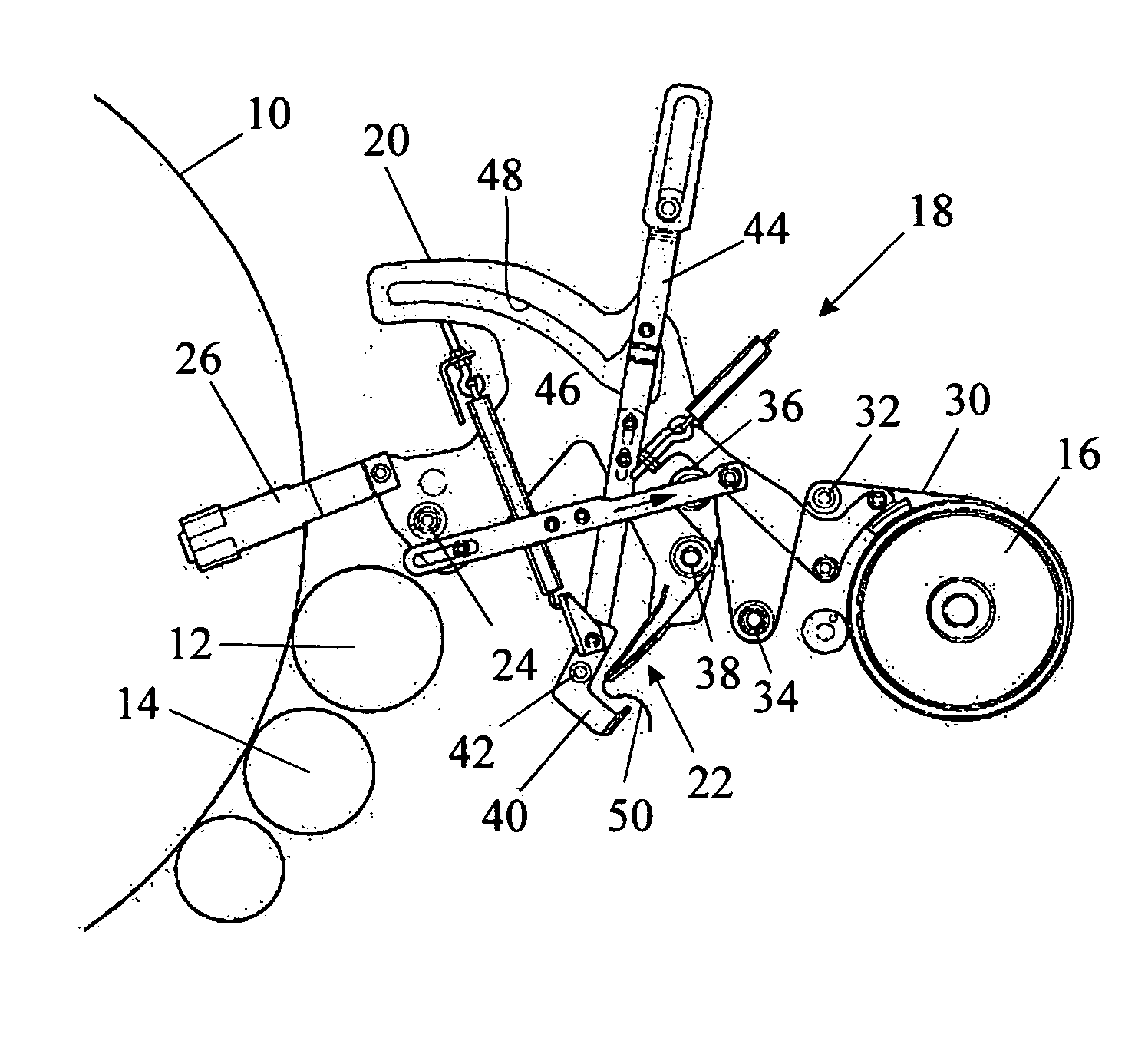
[0033] The drawings and following description concentrate on a wrapping mechanism for use in a baler. The remainder of the baler will not be described or illustrated in detail but it is mentioned for completeness that the baler may be as described in U.S. Pat. No. 4,956,968, which is incorporated herein by reference.

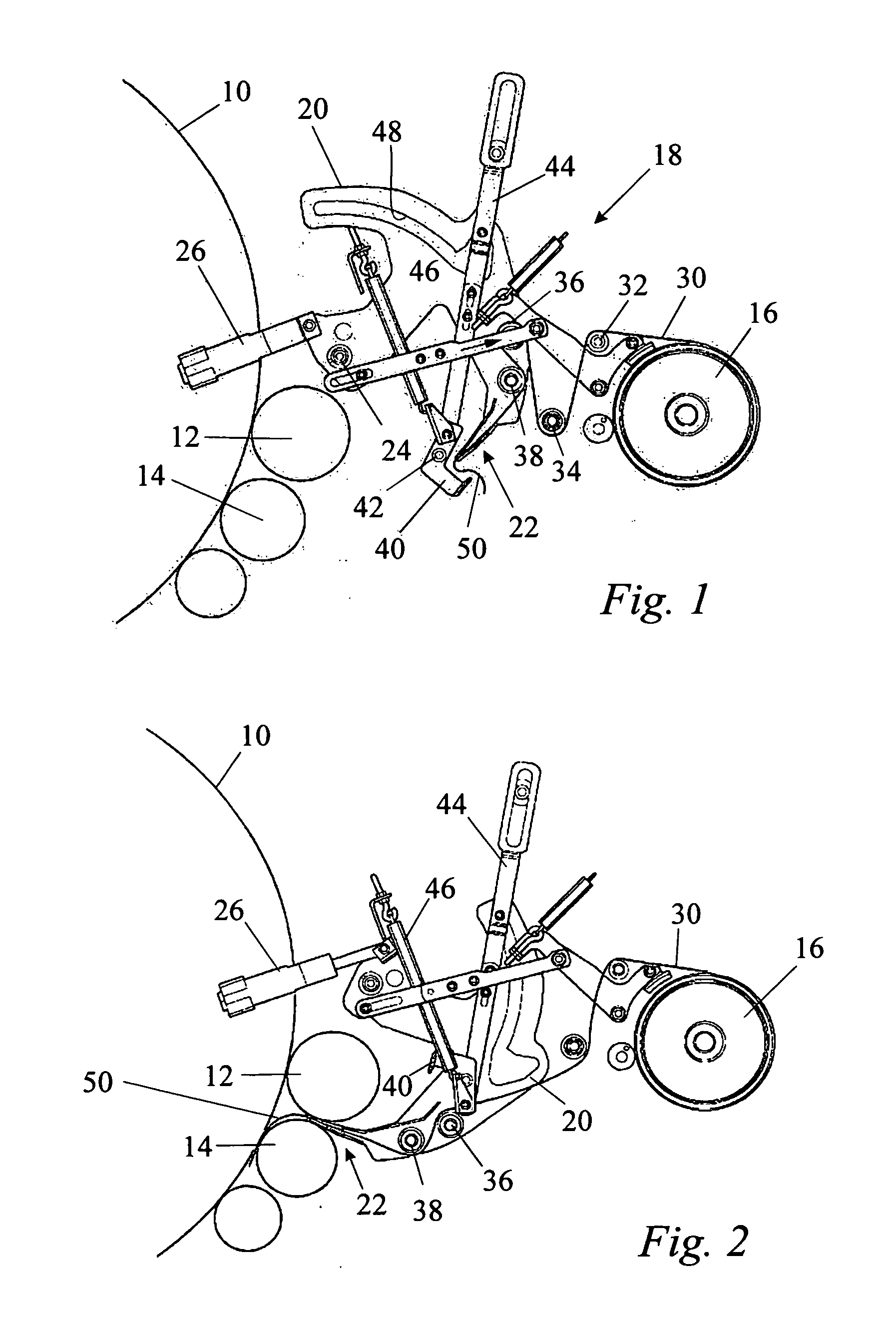
[0034] In accompanying FIG. 1, a bale being formed in the bale forming chamber of a round baler is designated 10. The bale 10 is caused to rotate within the chamber by various transverse rollers and / or belts of which only the two rollers designated 12 and 14 are relevant to the present invention. To wrap the bale 10, a wrapping material 30 drawn from a supply roll 16 is introduced by a feed mechanism generally designated 18 through the gap between the two rollers 12 and 14 into the bale forming chamber.

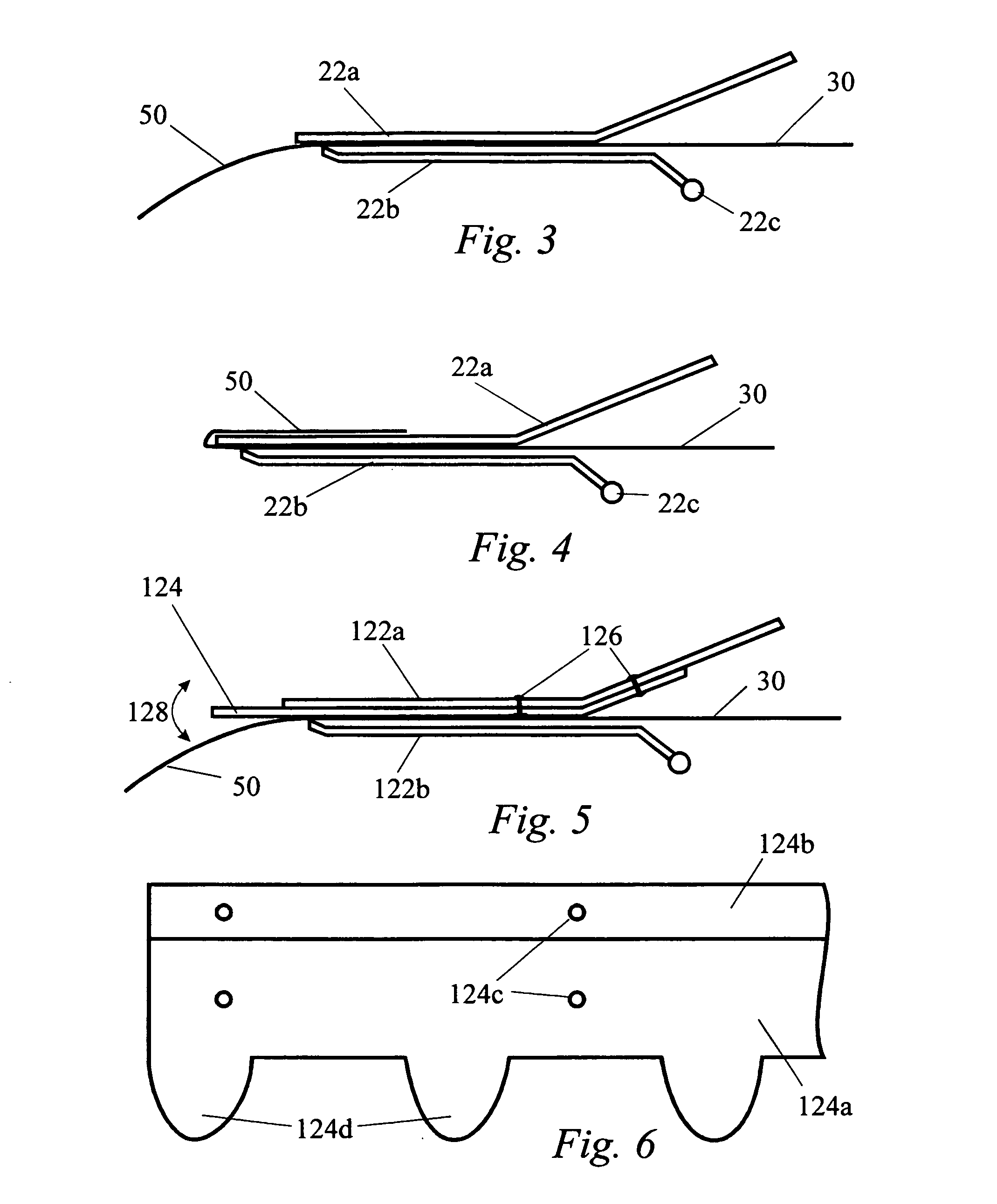
[0035] The feed mechanism comprises two end plates 20 arranged on opposite sides of the baler and a duck bill generally designated 22 which extends across the width of t...


PUM

PropertyMeasurementUnit
lengthaaaaaaaaaa
flexibleaaaaaaaaaa
diameteraaaaaaaaaa

Abstract

A device is disclosed for introducing the free end of a wrapping material into the bale forming chamber of a round baler. The device comprises a pair of elongate plates 122a and 122b that are biased towards one another to grip the wrapping material between them One of the plates 122a has a leading edge that projects further than the other in the feeding direction of the wrapping material 30. In the invention, the leading edge is formed with forward projecting resiliently flexible fingers 124d which are transversely spaced from one another.

Description

FIELD OF THE INVENTION [0001] The present invention relates generally to agricultural baling machines and more particularly to a round baler for producing cylindrical bales, commonly referred to as round bales, having an improved wrapping apparatus for wrapping a cylindrical package of crop material formed in a bale forming chamber. BACKGROUND OF THE INVENTION [0002] Round balers generally have a bale forming chamber defined by a pair of opposing side walls associated with an array of side-by-side belts, transverse slats trained on chains, a plurality of transverse rollers or a combination of these various elements, e.g. rollers and belts. During field operation, windrowed crop material such as hay is picked up from the ground and fed in a continuous stream into a fixed or variable diameter chamber. The hay is rolled into a cylindrical package within the chamber, wrapped with twine, netting or a plastics film and ejected onto the ground for subsequent handling. [0003] U.S. Pat. Nos....

Claims


Application Information

Patent Timeline
Patent Type & Authority Applications(United States)
IPC IPC(8): B65B11/56A01F15/07
CPCA01F15/0715
Inventor RYSE, JOHAN A. E. VANDE
Owner CNH IND AMERICA LLC
Why Eureka
Try Eureka