Easily demountable combustion chamber with improved aerodynamic performance

Active Publication Date: 2006-11-02
SN DETUDE & DE CONSTR DE MOTEURS DAVIATION S N E C M A
View PDF9 Cites 10 Cited by
  • Summary
  • Abstract
  • Description
  • Claims
  • Application Information

AI Technical Summary

Benefits of technology

[0004] The invention makes it possible to overcome these two difficulties.
[0007] For example, if tongues are used, the tongues of said caps are welded to the tongues of said chamber end wall. They are preferably welded together in pairs at their ends only. Under such conditions, any disassembly of the component elements of the combustion chamber can be performed easily by grinding the ends of the tongues so as to eliminate the weld zones.
[0008] Having separate tongues makes it possible to subdivide the combustion chamber into a plurality of portions, thus enabling repairs to be made on any one of said portions.
[0009] If the fastener parts are annular rims, it is advantageous to conserve a sectorized configuration, as when using tongues, e.g. by making a plurality of welds that are regularly distributed circumferentially. It is possible to combine annular rims and tongues.

Problems solved by technology

This disturbance penalizes the performance of the combustion chamber.
However, welding makes the combustion chamber difficult to repair since it is then necessary to cut said chamber along two circular welds.
Since the welds are located on cones, it is very difficult and expensive to reassemble the combustion chamber after repairing an element thereof.

Method used


Image

  • Easily demountable combustion chamber with improved aerodynamic performance
  • Easily demountable combustion chamber with improved aerodynamic performance
  • Easily demountable combustion chamber with improved aerodynamic performance

Examples


Embodiment Construction

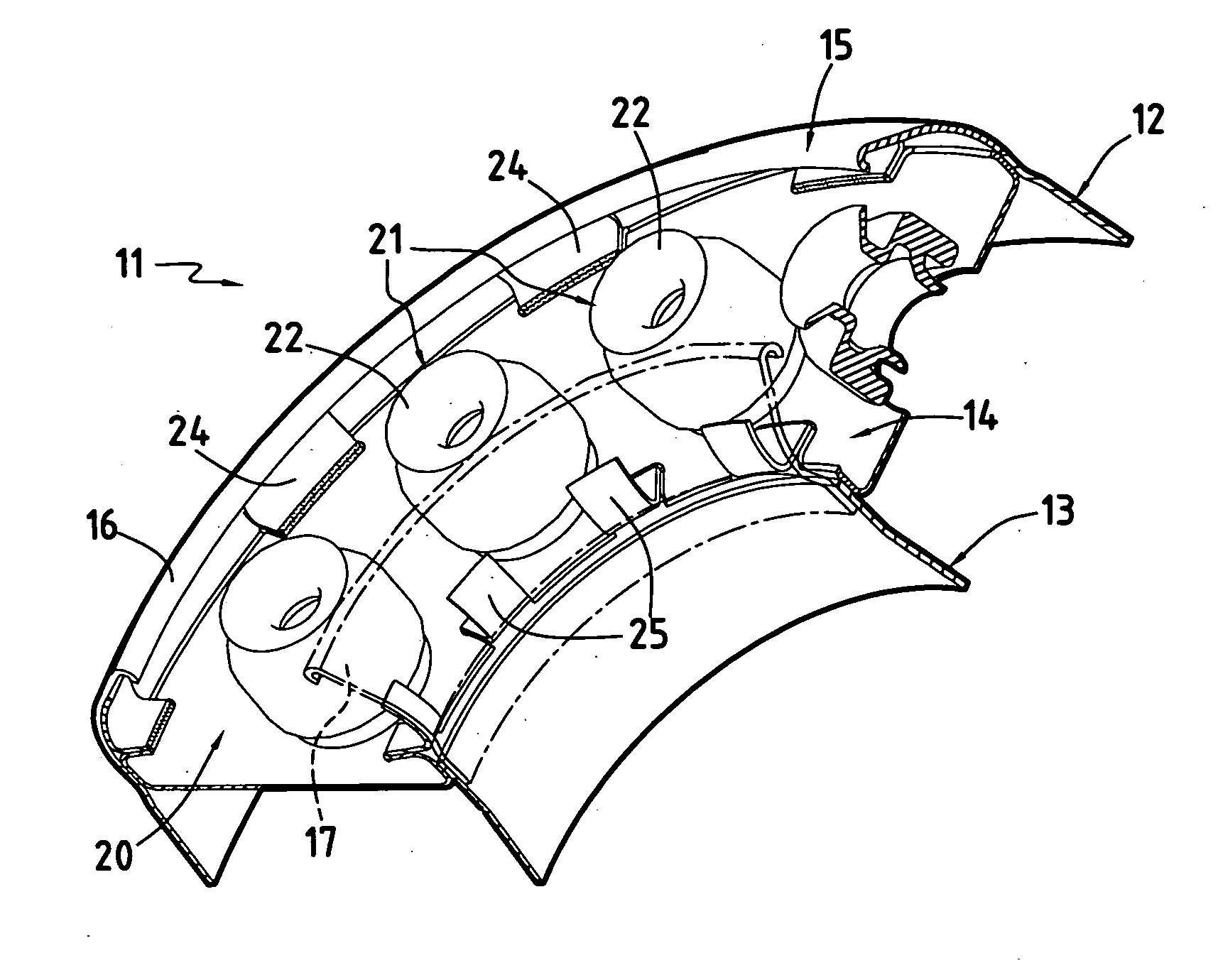
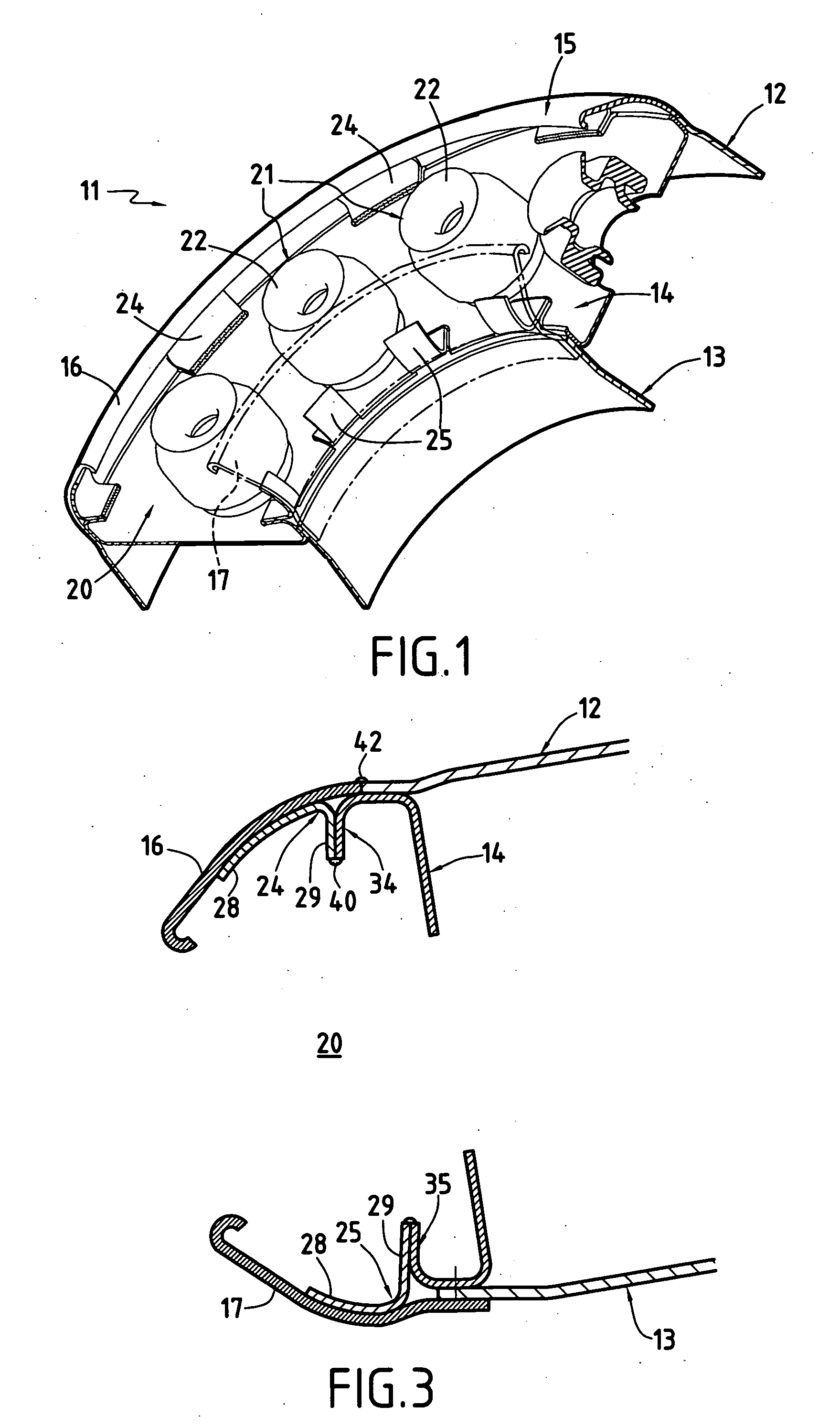
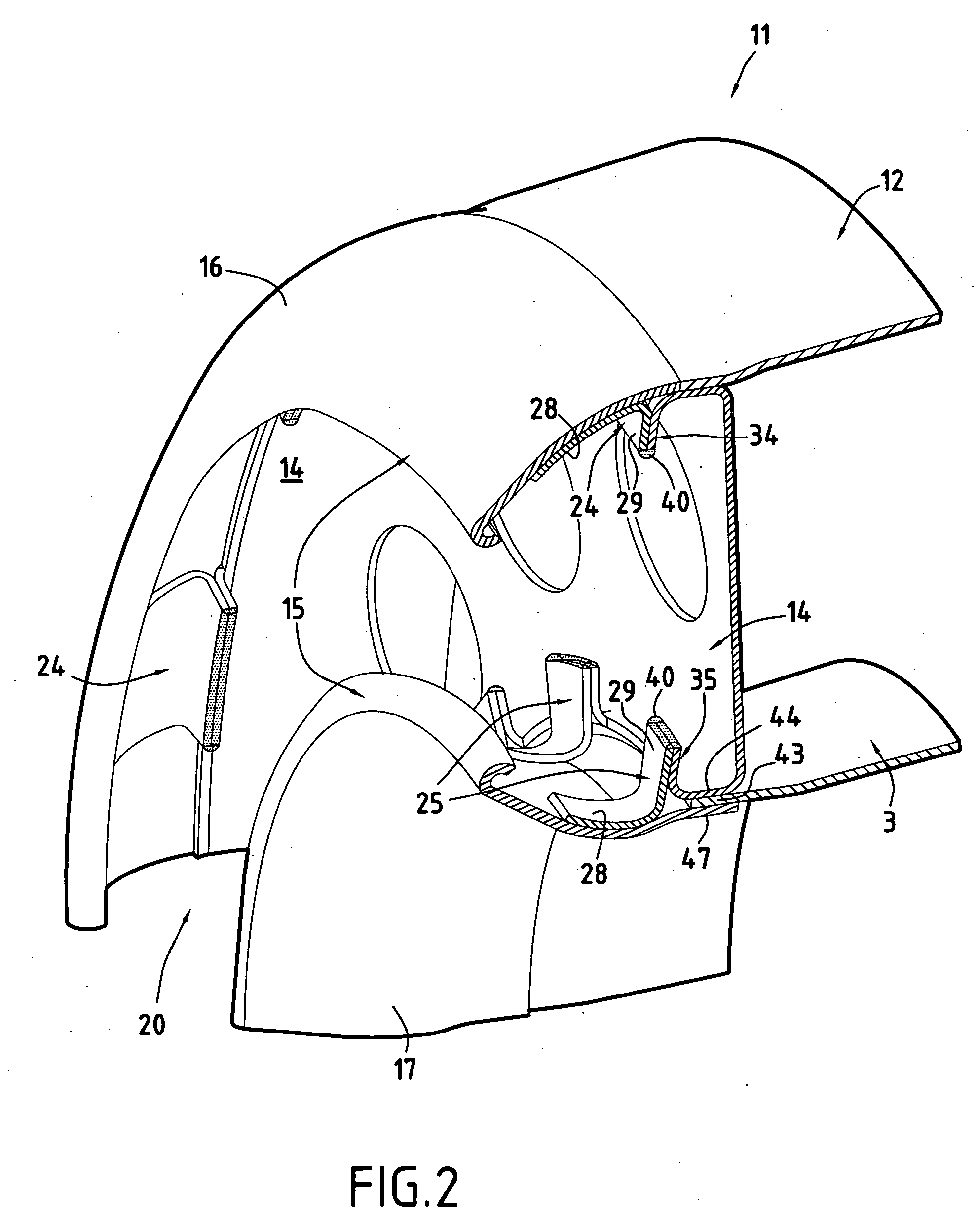
[0019] The drawings show a fragment of the front portion of a combustion chamber 11 that is made up by assembling together a plurality of annular parts. There can be seen a generally annular outer wall 12, a generally annular inner wall 13, a chamber end wall 14 extending between said outer and inner walls and having injector means 21 mounted thereon, and a fairing 15 comprising an annular part referred to as the “outer cap”16 and an annular part referred to as the “inner cap”17. The fairing co-operates with the chamber end wall to define an annular cavity 20 that houses the injector means. These means are constituted by a plurality of injectors 22 regularly spaced apart circumferentially and mounted on the chamber end wall 14.

[0020] The invention relates more particularly to the way in which said inner and outer walls, said chamber end wall, and the two caps are assembled together.

[0021] More particularly, the caps 16, 17 include respective tongues 24, 25 projecting into the annu...


PUM


Abstract

The component elements of a jet engine combustion chamber are assembled together in a manner that is designed to facilitate maintenance while also improving aerodynamic performance. In an embodiment, the outer cap and the inner cap have tongues and the chamber end wail has corresponding tongues, and the tongues of the caps are assembled to the tongues of the chamber end wall.

Description

[0001] This invention relates to a combustion chamber for a jet engine. It relates more particularly to an improvement in assembling the various portions of the combustion chamber, both in order to reduce disturbances to the flow of air around the chamber, which disturbances can be harmful to performance, and in order to facilitate maintenance of the chamber. BACKGROUND OF THE INVENTION [0002] A known combustion chamber is an assembly that can be divided into a plurality of portions. There is a generally annular outer wall, a generally annular inner wall, and a chamber end wall extending between said outer and inner walls. Fuel injector means are mounted on said chamber end wall. They are constituted by a plurality of injector systems that are spaced apart circularly. In addition, a fairing co-operates with the chamber end wall to define an annular cavity that houses the injector means. The combustion chamber as defined in this way constitutes an axially symmetrical assembly that ne...

Claims


Application Information

Patent Timeline
IPC IPC(8): F02C3/14F02C3/04
CPCF23R3/50F23R3/002F23R3/60F23R3/10F23R2900/00017
Inventor PIEUSSERGUES, CHRISTOPHESABLAYROLLES, PIERRE PASCALMARNAS, LAURENT PIERRE, ELYSEE, GASTON
Owner SN DETUDE & DE CONSTR DE MOTEURS DAVIATION S N E C M A
Why Eureka
Try Eureka