System and method for dynamic impedance tuning to minimize return loss

a dynamic impedance and return loss technology, applied in the field of signal processing, can solve problems such as difficult impedance matching, and achieve the effects of minimizing return loss, impedance matching, and minimizing system return loss

Active Publication Date: 2006-11-02
CSR TECH INC
View PDF6 Cites 0 Cited by
  • Summary
  • Abstract
  • Description
  • Claims
  • Application Information

AI Technical Summary

Benefits of technology

[0004] In accordance with another embodiment of the present invention, a system for minimizing return loss comprises a plurality of components coupled to each other at a node. Each component is associated with a first impedance when the component is operating and a second impedance when the component is not operating. The system further comprises an impedance tuning circuit coupled to the plurality of components at the node and an impedance matching circuit coupled to the node. The impedance tuning circuit is operable to tune an impedance at the node based upon at least some of the first impedances of the plurality of components and further based upon at least some of the second impedances of the plurality of components. The impedance matching circuit is operable to minimize a return loss of the system across a broadband range of frequencies based at least in part upon the impedance at the node.
[0005] The following technical advantages may be achieved by some, none, or all of the embodiments of the present invention. Impedance matching can be difficult when the input impedance of a circuit can vary according to the operation of the components in the circuit. In the system of the present invention, an impedance tuning circuit facilitates the tuning of an input impedance of an integrated circuit to within a consistent range of input impedances no matter which components of the integrated circuit are operating. As a result, an input matching circuit that is external to the integrated circuit may be used to minimize the return loss of the system across a broadband range of frequencies. These and other advantages, features, and objects of the present invention will be more readily understood in view of the following detailed description and the drawings.

Problems solved by technology

Impedance matching can be difficult when the input impedance of a circuit can vary according to the operation of the components in the circuit.

Method used


Image

  • System and method for dynamic impedance tuning to minimize return loss
  • System and method for dynamic impedance tuning to minimize return loss

Examples


Embodiment Construction

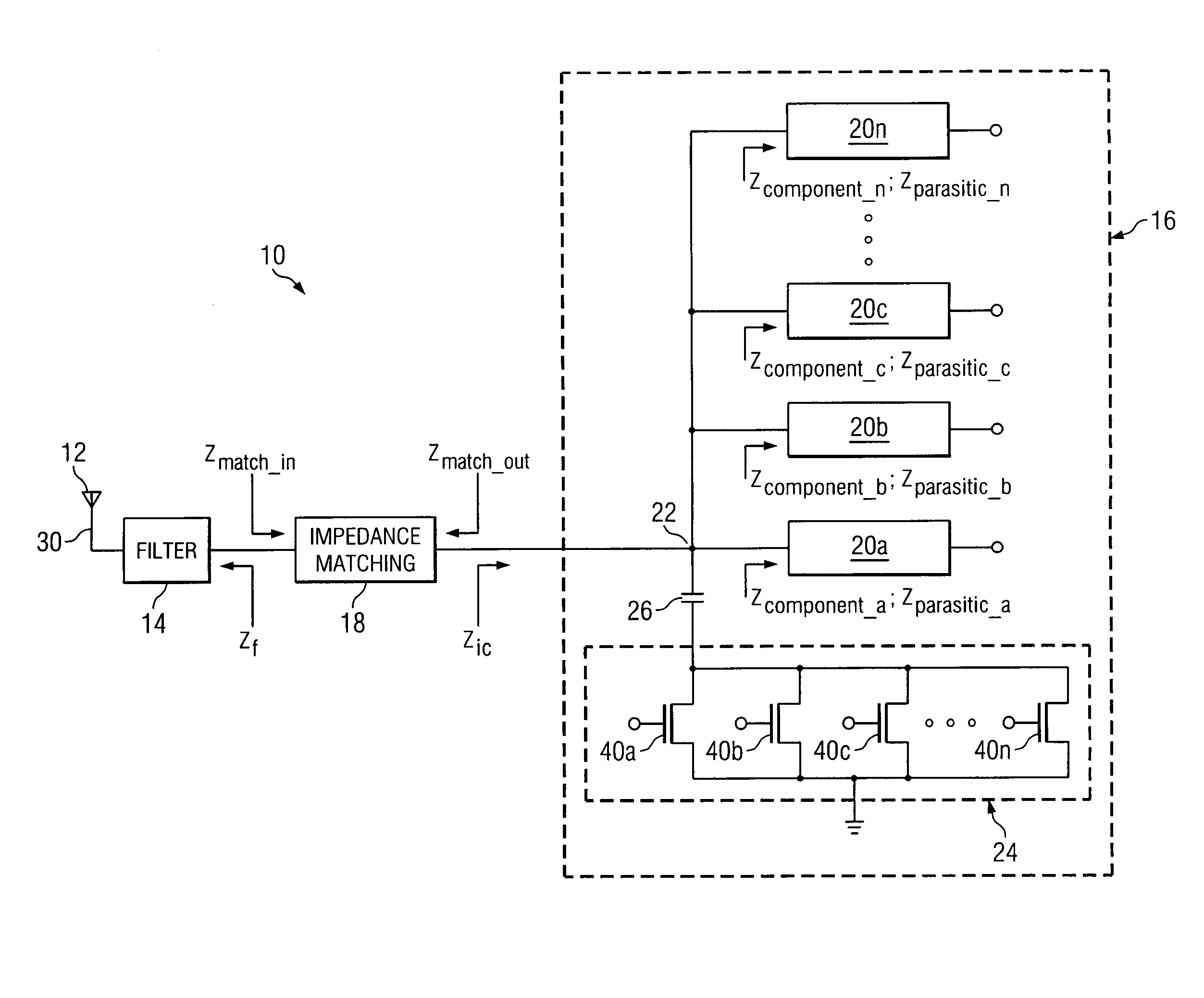
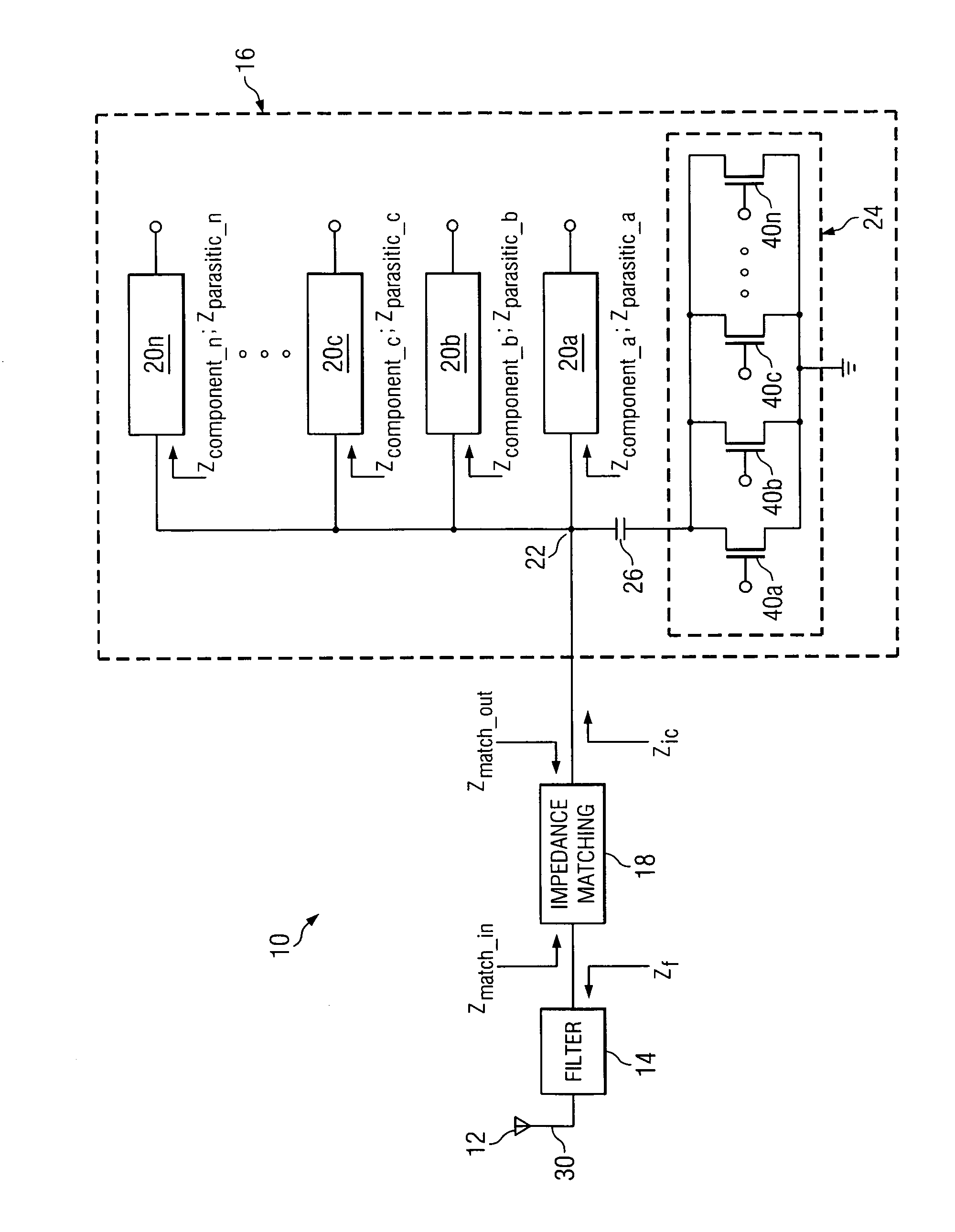
[0008]FIG. 1 illustrates a system 10 that includes an input device 12 coupled to a filter 14 which is further coupled to components of an integrated circuit 16 by an impedance matching circuit 18. Integrated circuit 16 comprises components 20a-20n coupled to each other at an input node 22. Circuit 16 further comprises an impedance tuning circuit 24 that is AC-coupled to input node 22 using a capacitor 26. In general, the filter 14 exhibits a filter output impedance, Zf, and the components of the integrated circuit 16 exhibit an integrated circuit input impedance, Zic. Impedance tuning circuit 24 facilitates control of Zic at input node 22 such that impedance matching circuit 18 can be used to minimize the return loss of system 10 across a broadband range of frequencies, no matter which components 20a-20n are turned on or off.

[0009] Input device 12 comprises a terrestrial antenna, a cable input, a satellite dish, or any other suitable device for receiving a broadband signal 30 from ...


PUM


Abstract

A system for tuning an impedance at a node comprises a first component associated with a first impedance when the first component is operating and a second impedance when the first component is not operating. The system further comprises a second component coupled to the first component at a node. The second component is associated with a third impedance when the second component is operating and a fourth impedance when the second component is not operating. An impedance tuning circuit is coupled to the second component at the node and operable to tune an impedance at the node based at least in part upon a plurality of the first impedance, the second impedance, the third impedance, and the fourth impedance.

Description

TECHNICAL FIELD OF THE INVENTION [0001] This invention relates in general to signal processing and more particularly to a system for dynamic impedance tuning to minimize return loss. BACKGROUND OF THE INVENTION [0002] Impedance is a measure of the overall opposition of a circuit to current. It is like resistance, but it also takes into account the effects of capacitance and inductance. Impedance is more complex than resistance because the effects of capacitance and inductance vary with the frequency of the current passing through the circuit and this means impedance varies with frequency. The effect of resistance is constant regardless of frequency. Therefore, by adding or subtracting capacitance or inductance to a circuit, we can change the impedance of the circuit. SUMMARY OF THE INVENTION [0003] In accordance with one embodiment of the present invention, a system for tuning an impedance at a node comprises a first component associated with a first impedance when the first compone...

Claims


Application Information

Patent Timeline
Patent Type & Authority Applications(United States)
IPC IPC(8): H04B1/40H04B1/46
CPCH04L25/0278H03H7/40H03H7/38H04B1/10
Inventor WOMAC, MICHAEL D.
Owner CSR TECH INC
Why Eureka
Try Eureka