Emergency rescue equipment comprising a harmonic reflector circuit

a technology of harmonic reflector and emergency rescue equipment, which is applied in the direction of reradiation, instruments, sport apparatus, etc., can solve the problems of poor impedance match between the reflector antenna and the non-linear element, performance degradation, and poor impedance match, so as to improve the safety of users and improve the effect of impedance match

Pending Publication Date: 2022-03-10
RECCO INVEST
View PDF0 Cites 0 Cited by
  • Summary
  • Abstract
  • Description
  • Claims
  • Application Information

AI Technical Summary

Benefits of technology

[0013]The present invention provides an emergency rescue equipment having a harmonic reflector circuit comprising an antenna connected to a non-linear circuit via a matching circuit and a casing that full or in part encloses the harmonic reflector circuit, wherein the harmonic reflector circuit is configured to receive a signal at a receive frequency (fRX), and configured to re-transmit said received signal at a transmit frequency (fTX), where the transmit frequency is a multiple of the receive frequency, wherein the receive frequency (fRX) is in an interval from a first frequency to a second frequency, where: the first frequency is at least 800 MHz; and the second frequency is at least 34 MHz higher than the first frequency; the received signal is transmitted at the transmit frequency (fTX) with an output power (Pout) of at least 70% of the maximum available output power (Pmax) for a frequency in the transmit frequency range from the multiple of the first frequency to the same multiple of the second frequency. This allows detection of objects with large differences in material and size, due to the broadband behaviour of the harmonic reflector circuit. Using an emergency rescue equipment in an environment with varied electromagnetic properties may degrades the performance. This degradation is due to the change in the electromagnetic properties result in different antenna impedance, resulting in a poor impedance match between the reflector antenna and the non-linear element. For example, such varied electromagnetic properties may for example be by enclosing the harmonic reflector circuit in casings of different materials, by having different material between the harmonic reflector circuit and the signal that is transmitted by the rescue team or by different humidity's. By utilizing a harmonic reflector circuit with a broadband behaviour, the emergency rescue equipment may be detected in in a wide span of surroundings where prior art equipment tuned for a specific receive frequencies would be vulnerable. For example, by utilizing a harmonic reflector circuit with a broadband behaviour, the emergency rescue equipment would be more robust and be functional in more numerous types of casings and situations. Thereby the safety of the user can be increased.

Problems solved by technology

When the reflector is placed in an environment with different properties the performance will be degrade.
This is mainly due to that the change in the electromagnetic properties result in different antenna impedance, resulting in a poor impedance match between the reflector antenna and the non-linear element.
Using an emergency rescue equipment in an environment with varied electromagnetic properties may degrades the performance.
This degradation is due to the change in the electromagnetic properties result in different antenna impedance, resulting in a poor impedance match between the reflector antenna and the non-linear element.

Method used


Image

  • Emergency rescue equipment comprising a harmonic reflector circuit
  • Emergency rescue equipment comprising a harmonic reflector circuit
  • Emergency rescue equipment comprising a harmonic reflector circuit

Examples


Embodiment Construction

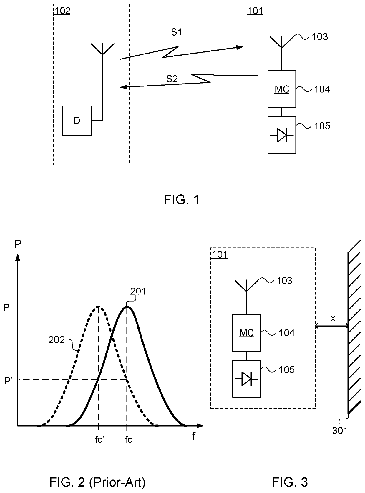
[0051]FIG. 1 shows a harmonic reflector circuit, generally designated 101, and a detector, generally designated 102.

[0052]The detector 102 transmits a signal S1 at a frequency fRX this signal S1 is received by the harmonic reflector circuit 101 and converted and transmitted as a second signal S2 at a frequency fTX by the harmonic reflector circuit 101. The harmonic reflector circuit 101 receives the incoming signal S1 by means of an antenna 103. The antenna 103 is connected to a matching circuit 104 which provides an impedance match between the antenna 103 and the non-linear circuit 105 for both the frequency fRX and the frequency fTX. The impedance matching is crucial for a conversion with low losses from the first signal S1 to the second signal S2, at their frequency fRX and fTX, respectively.

[0053]In FIG. 2 a typical response from the harmonic reflector 102 is disclosed. A first curve 201 shows the reflected power P from a signal transmitted at frequency fc, the bandwidth of the...


PUM


Abstract

An emergency rescue equipmenthaving a harmonic reflector circuit comprising an antenna connected to a non-linear circuit via a matching circuitand a casing that in part enclose the harmonic reflector circuit, wherein the harmonic reflector circuit is configured to receive a signal at a receive frequency (fRX), and configured to transmit said received signal at a transmit frequency (fTX), where the transmit frequency is a multiple of the receive frequency, the harmonic reflector circuit wherein the receive frequency (fRX) is in an interval from a first frequency to a second frequency, where the first frequency is at least 800 MHz; middle second frequency is at least 34 MHz larger than the first frequency;the received signal is transmitted at the transmit frequency (fTX) with an output power (Pout) of at least 70% of the maximum available output power (Pmax).

Description

TECHNICAL FIELD[0001]The present invention relates to an emergency rescue equipment having a radar reflector, and particularly to an emergency rescue equipment having a radar reflector for harmonic radar.BACKGROUND[0002]Emergency rescue equipment having harmonic radars have been used for a long time in search and rescue operations throughout the world. In a typical avalanche scenario, a skier is lost in an avalanche and a rescue team arrives shortly thereafter, the skier is equipped with an emergency rescue equipment having a reflector. The rescue team is equipped with a detector that transmits a signal with a transmit frequency. When the reflector on the skier receives this signal, the reflector converts the frequency of the signal to a multiple thereof and transmit the converted signal back to the detector. This means that the detector transmits on a first frequency and receives on a multiple of the first frequency, this information is then used to determine the position of the sk...

Claims


Application Information

Patent Timeline
Patent Type & Authority Applications(United States)
IPC IPC(8): G01S13/34G01S13/75G08B25/01H01Q1/24H01Q1/27
CPCG01S13/34G01S13/753H01Q1/273H01Q1/241G08B25/016G01S13/887G01S7/03A63B29/021A43B5/0496A43B3/34H01Q1/2225H01Q1/38H01Q1/276H01Q5/50G01S13/02G01S13/82H04B1/59
Inventor GRANHED, MAGNUSFORSSÉN, TOMAS
Owner RECCO INVEST
Why Eureka
Try Eureka