ECG cable for use in MRI

a technology of ecg cable and mri, applied in the field of monitor cables, can solve problems such as current generation, patient or clinician injury, and “r” wave detection

Inactive Publication Date: 2006-11-02
IVY BIOMEDICAL SYST
View PDF8 Cites 39 Cited by
  • Summary
  • Abstract
  • Description
  • Claims
  • Application Information

AI Technical Summary

Benefits of technology

[0010] The invention relates to a cable for use in monitoring patients in an MRI environment. In one embodiment, the cable is constructed of a flexible substrate on which are drawn conductive traces with a conductive ink. In one embodiment, the flexible substrate is Kapton. In one embodiment the conductive ink is a carbon ink. In...

Problems solved by technology

Each of these fields presents a special challenge for the accurate detection of the “R” wave of the ECG signal.
This presents the problem that magnetic items near the bore of the magnet can become projectiles with the resulting patient or clinician injury.
There is also a secondary problem with respect to “R” wave detection.
Yet a second problem is caused by the moving magnetic field gradients, since they will cause currents to be generated in any conductor exposed to them.
The use of patient leads and cables inside the MRI bore to bring the low level (typically 1 mV) ECG signal to the amplifiers, results in artifacts in the ECG signal that could be in the same bandwidth as the ECG signal itself.
Finally, the pulsed RF fields present the greatest challenge to effective ECG detection.
These RF pulses, ...

Method used


Image

  • ECG cable for use in MRI
  • ECG cable for use in MRI

Examples


Embodiment Construction

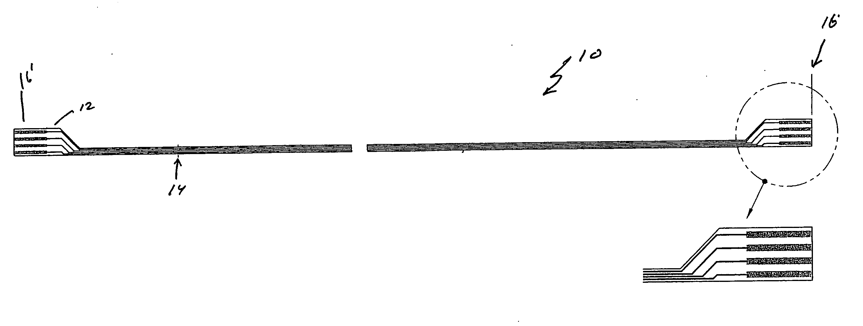
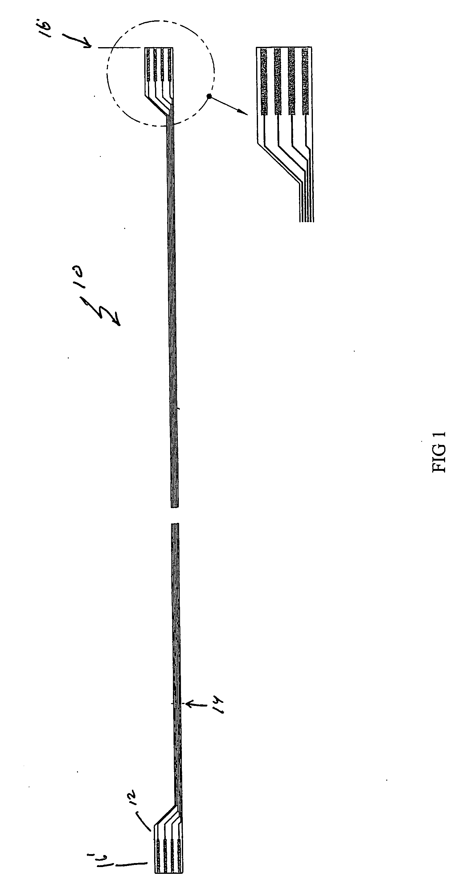
[0014] Referring to FIG. 1, a cable constructed in accordance with the invention includes a cable 10 constructed of a flexible substrate 12 on which are drawn conductive traces 14 with a conductive ink. (Ohmega Technologies, Culver City, Calif.). In one embodiment the flexible substrate is Kapton. In one embodiment the conductive ink is a carbon ink. In one embodiment, the carbon ink has a resistance of 10 ohms / sq. In one embodiment, the cable has an impedance of 10,000 ohms / ft.

[0015] In the embodiment shown the cable is a six foot long cable for use with an ECG monitor. As such the cable has four traces to conduct the signals to an ECG monitor. The two ends of the cable 16, 16′ include an expanded region with copper pads to permit one end of the cable to connect to an ECG electrode and the other end to connect to an ECG monitor.

[0016] Although the invention is described in terms of an n ECG monitor cable, the cable with the appropriate number of conductors can connect sensors on ...


PUM


Abstract

A cable for use in monitoring patients in an MRI environment. In one embodiment the cable is constructed of a flexible substrate on which are drawn conductive traces with a conductive ink. In one embodiment the flexible substrate is Kapton. In one embodiment the conductive ink is a carbon ink. In one embodiment the carbon ink has a resistance of 10 ohms/sq. In one embodiment the cable has a distributed impedance of 10,000 ohms/ft.

Description

RELATED APPLICATIONS [0001] This application claims priority to and benefit of U.S. Provisional application 60 / 675,951, filed on Apr. 28, 2005, the entirety of the application is incorporated by reference herein.FIELD OF THE INVENTION [0002] This invention relates to the field of monitor cables and more specifically to the field of monitor cables to be used in an MRI environment. BACKGROUND OF THE INVENTION [0003] Due to recent advances in Magnet Resonance Imaging (MRI), there is a growing interest in using MRI to image the heart. Because the MRI image is very sensitive to motion from slice to slice, and stopping the heart is impractical, it is necessary to accurately detect the peak of the “R” wave of the ECG signal to generate a trigger signal and thereby insure that each image slice is taken when the heart is in the same relative position. [0004] The traditional approach has been to use non-metallic electrodes and patient leads to bring the ECG signal out of the bore of the magne...

Claims


Application Information

Patent Timeline
IPC IPC(8): A61B5/04A61B5/308
CPCA61B2562/222A61B5/04286A61B5/303
Inventor TUCCILLO, MARK JOSEPHBLANK, ELLIOT JAY
Owner IVY BIOMEDICAL SYST
Why Eureka
Try Eureka