

Motor vehicle-detecting system
a detection system and motor vehicle technology, applied in the direction of analogue processes, instruments, specific applications using reradiation, etc., can solve the problems of difficult precision detection of vehicles, detectors that are not applicable to a place, and buried work, so as to reduce power consumption and cost, maintain the effect of accuracy and small power consumption
- Summary
- Abstract
- Description
- Claims
- Application Information
AI Technical Summary
Benefits of technology
Problems solved by technology
Method used
Image

Examples
example 1
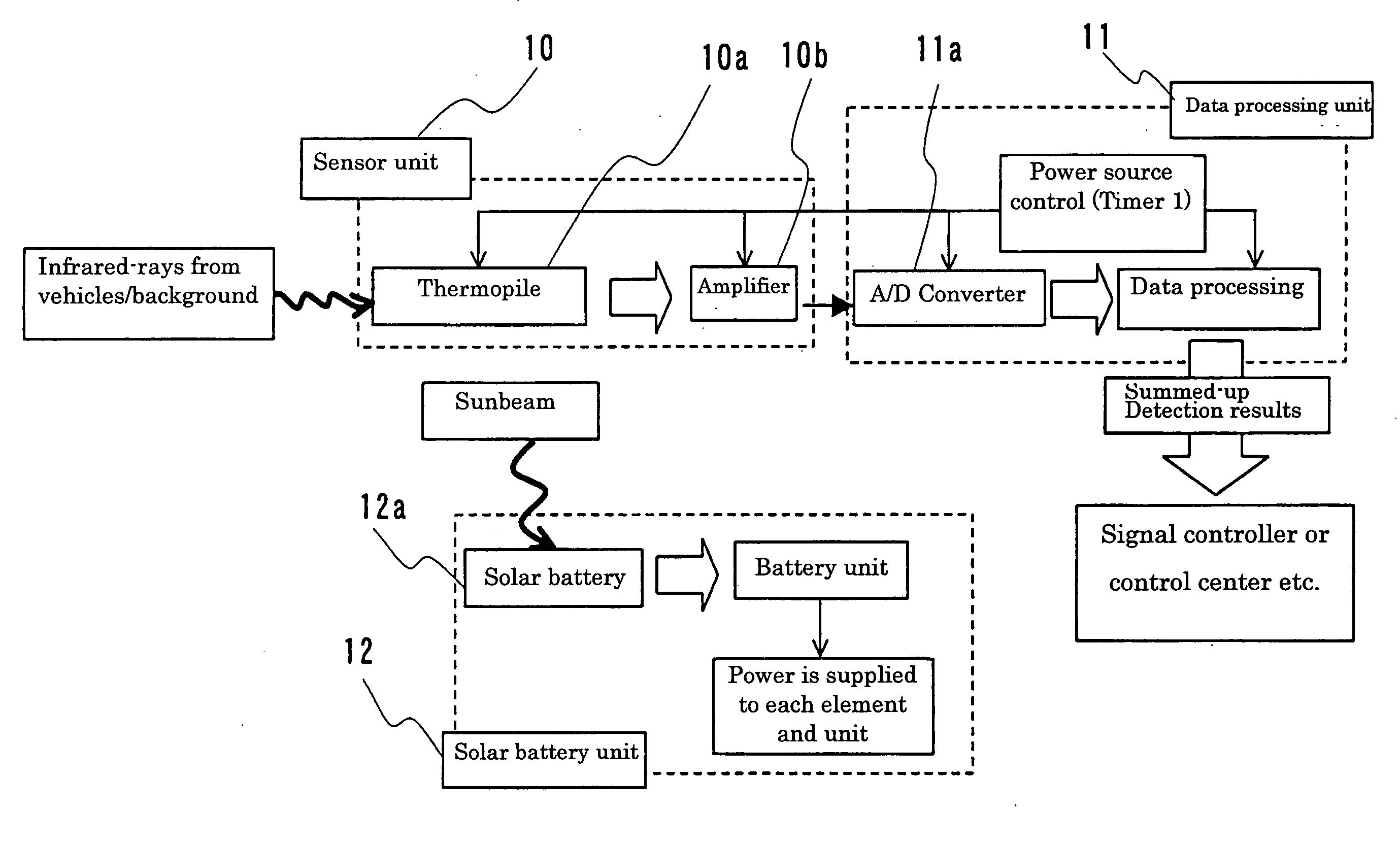
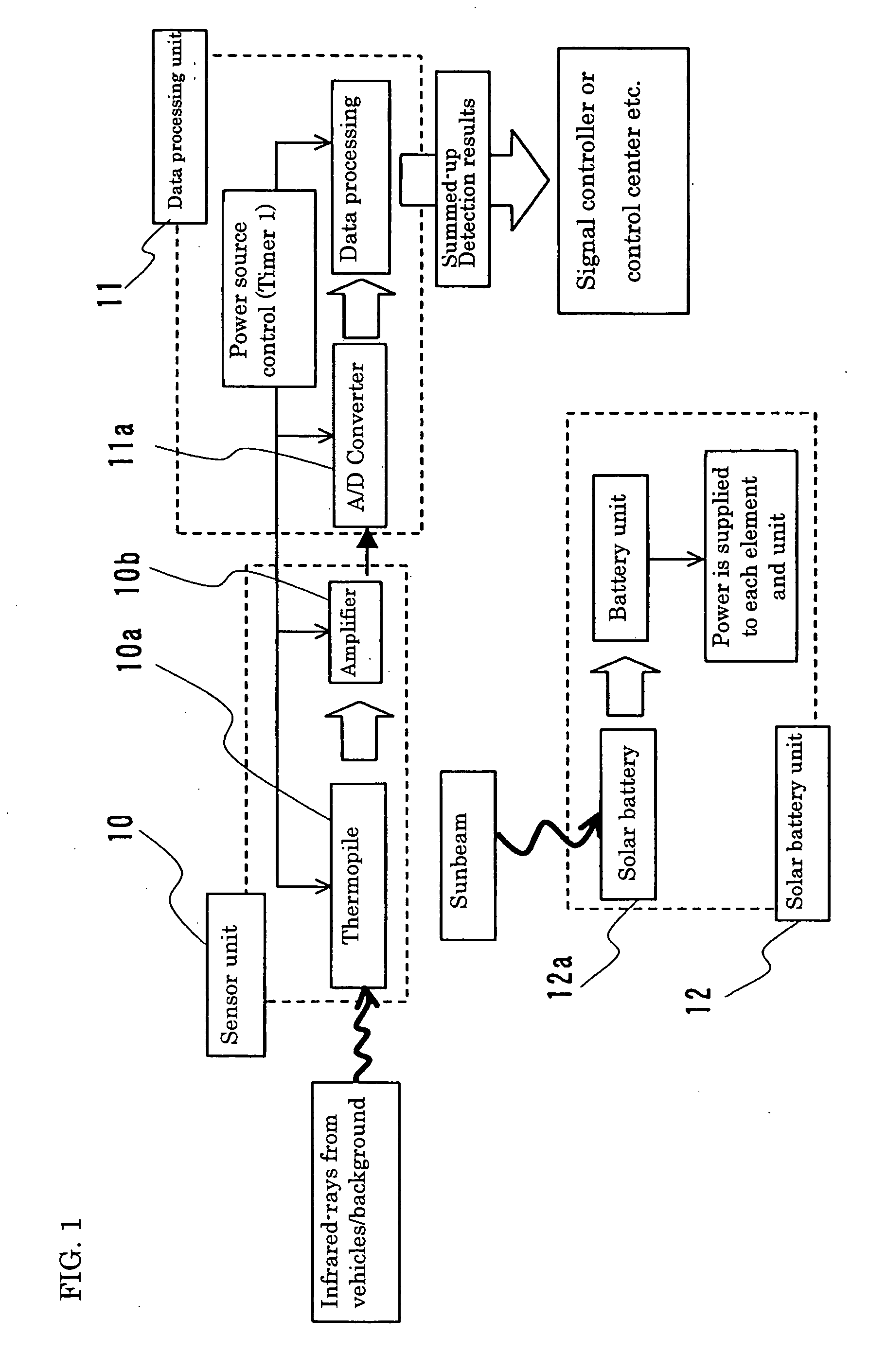
[0117]FIG. 1 is a functional block diagram illustrating the operation of a vehicle detection system of the present invention in the case of intermittently operating a sensor by timer control and transmitting summed-up results through wire. This system detects infrared radiation irradiated from vehicles, etc., compares the detected result (an input level value) with a background level value, and determines the vehicle presence by comparing the difference between the input level value and the background level value with a threshold value. In this example, the difference between the input level value and the background level value is directly used as a comparative value, that is, a value based on the difference between the input level value and the background level value. Specifically, configured elements are as follows:
(1) Sensor Unit 10
[0118] In this example, a thermopile 10a is used as a sensor for detecting infrared radiation irradiated from an object such as a vehicle or the roa...
example 2
[0129] In Example 1, the summed-up detected results are transmitted to signal controllers and a control center, etc. by wire. However, by providing a radio communication unit (a radio communication means), these results may be transmitted by light such as infrared radiation or by radio.
[0130]FIG. 4 is a functional block diagram of a vehicle detection system of the present invention having a radio communication unit; in the system, the sensor is intermittently operated by timer control. The basic configuration of the system is similar to the one illustrated in FIG. 1, the difference being that radio communication unit 13 is provided. The radio communication unit 13 having a radio control unit 13a and a transmission / reception unit 13b with an antenna, etc. transmits the summed-up detected results transmitted from the data processing unit 11 to signal controllers or a control center, and so on. In this example, electricity is intermittently supplied for a predetermined period at a pre...
application example
[0197] Detection of vehicles running on one traffic lane An application example of the vehicle detection system of the present invention is explained as follows.
[0198]FIG. 19 is a schematic diagram illustrating a state in which a detector for the vehicle detection system of the present invention is installed on a supporting pole at the side of the road; FIG. 19 (A) is an example where a sensor and a vehicle presence judgment means are provided integrally in the detector, and FIG. 19 (B) is an example where they are provided separately. The detector 1, which is structured such that the thermopile 10a as the sensor described above and the data processing unit 11 for judging the presence of a vehicle are both put in the housing box 2, detects vehicle presence with a series of the processing procedures explained in the above examples when the housing box 2 is installed on a supporting pole 200 as shown in FIG. 19 (A). A detector 1′, which is configured such that only the thermopile 10a...
PUM
 Abstract
Description
Claims
Application Information