Eureka AIR delivers breakthrough ideas for toughest innovation challenges, trusted by R&D personnel around the world.

Method and apparatus for measurement of transmitter/receiver separation

a transmitter and receiver technology, applied in electrical equipment, medical science, sensors, etc., can solve the problems of conductive hearing loss, unable to derive suitable benefit from conventional hearing aid systems, and impede the normal mechanical pathway for sound to reach the hair cells in the cochlea, so as to improve the perforation of the implant system and improve the battery life

Inactive Publication Date: 2007-05-03
COCHLEAR LIMITED
View PDF6 Cites 41 Cited by
  • Summary
  • Abstract
  • Description
  • Claims
  • Application Information

AI Technical Summary

Benefits of technology

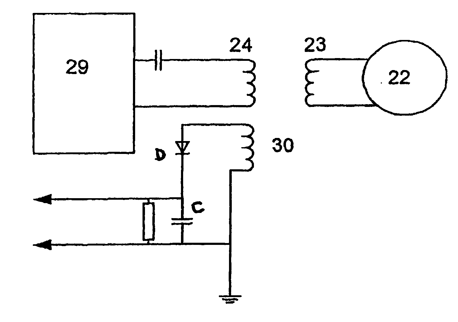
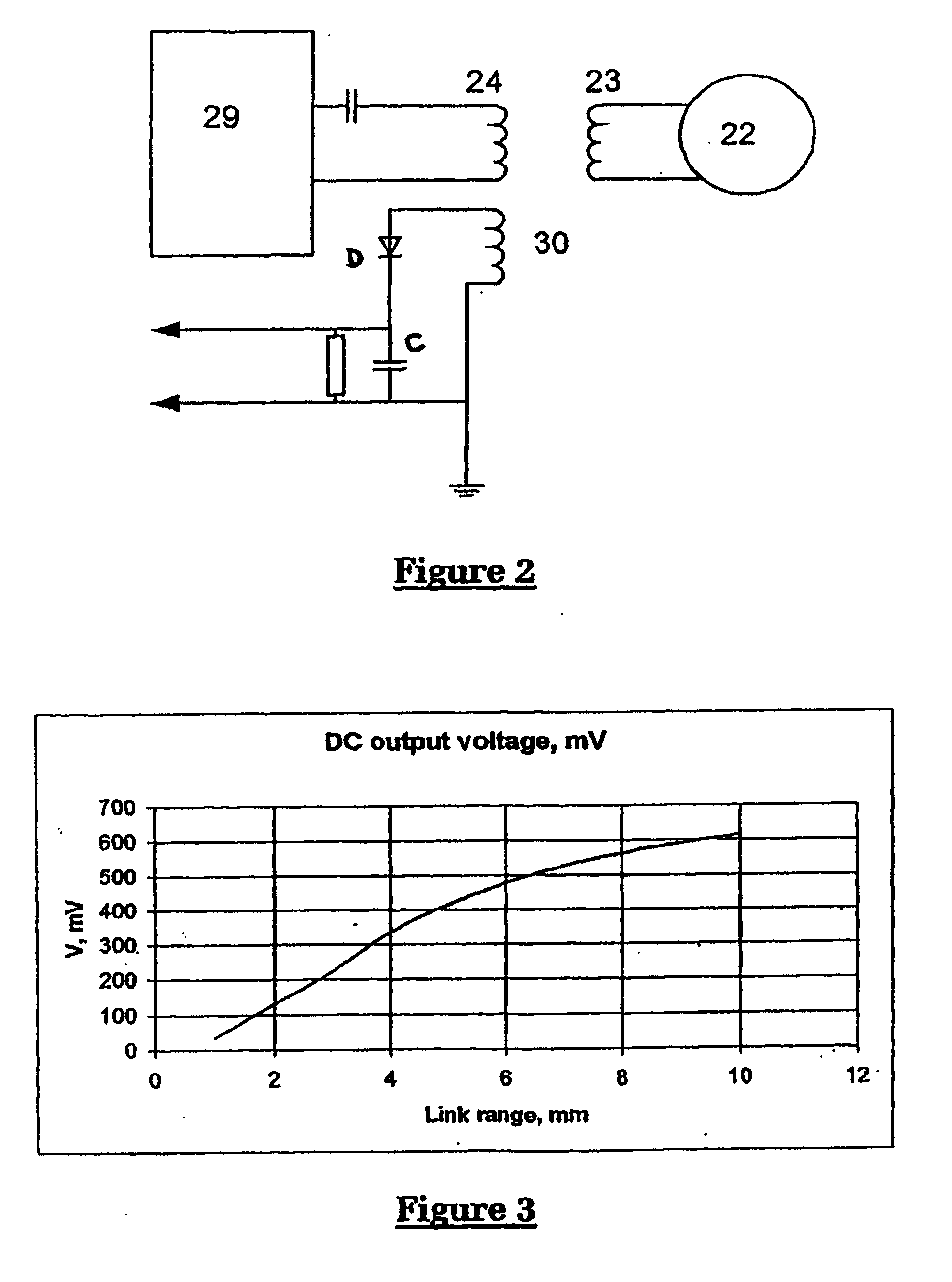
[0019] Further, a measurement of magnetic field strength can be performed with very little power consumption, and with very little loading effect on the transmissions between the external and implanted transceivers, thus providing the advantages of simple low current implementation.
[0023] Alternatively, the position of the external transceiver relative to the implanted transceiver may be determined in order to estimate a distance of separation between the external transceiver and the implanted transceiver. Such embodiments of the invention may be particularly advantageous, as the distance between the transceivers impacts upon the amount of power that can be delivered to the implanted transceiver, and hence impacts upon a power source current and useful life, for instance where the power source is a battery. As such embodiments of the present invention enable a determination of the distance to be made, transmission and stimulation parameters of transmissions between the transceivers may be optimised to allow for the actual distance of separation. Optimising such parameters for the actual distance of separation leads to improved perfornance of the implant system, and also improves battery lifetime.

Problems solved by technology

Of these types, conductive hearing loss occurs where the normal mechanical pathways for sound to reach the hair cells in the cochlea are impeded, for example, by damage to the ossicles.
These people are thus unable to derive suitable benefit from conventional hearing aid systems, no matter how loud the acoustic stimulus is made, because there is damage to or absence of the mechanism for nerve impulses to be generated from sound in the normal manner.
Aother problem is when an external transmitter or transceiver has been displace,. for example when the external transceiver has fallen away from an optimum position upon the recipient.
It is particularly relevant when the recipient, such as an infant, is unable to or unlikely to indicate such an occurrence and therefore cannot derive maximum hearing benefit from the implant system.
While an alternative prior art approach is to monitor a voltage standing wave ratio (VSWR) on the cable leading to the transmitter, such an approach requires an assumption that a change in the VSWR stems from an alteration in the link between the transmitter and receiver, whereas in fact such alterations in the VSWR may equally arise from a break in the cable or transmitter coil causing an open circuit or other such fault.
However, measurement and monitoring of battery current may not change monotonically with varying transceiver separation, and therefore does not enable a one-to-one mapping of battery current to the separation.

Method used


Image

  • Method and apparatus for measurement of transmitter/receiver separation
  • Method and apparatus for measurement of transmitter/receiver separation
  • Method and apparatus for measurement of transmitter/receiver separation

Examples


Embodiment Construction

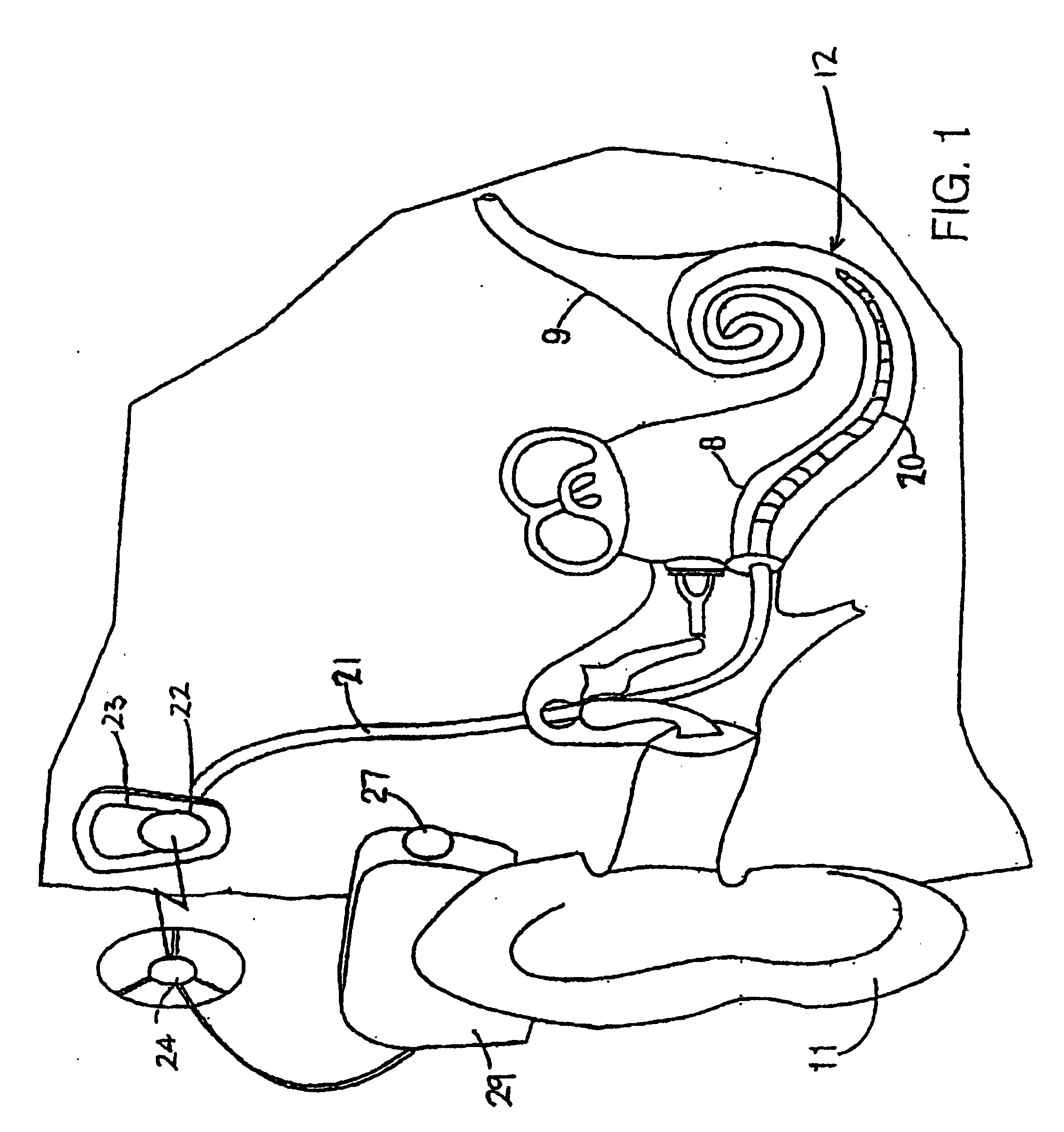
[0062] While the present invention is not directed solely to a cochlear implant, it is appropriate to briefly describe the construction of one type of known cochlear implant system with reference to FIG. 1.

[0063] Known cochlear implants typically consist of two main components, an external component including a speech processor 29, and an internal component including an implanted receiver and stimulator unit 22. The external component includes a microphone 27. The speech processor 29 is, in this illustration, constructed and 15 arranged so that it can fit behind the outer ear 11. Alternative versions may be worn elsewhere on the recipient's body. Attached to the speech processor 29 is a transmitter coil 24 that transmits electrical signals to the implanted unit 22 via a radio frequency (RF) link.

[0064] The implanted component includes a receiver coil 23 for receiving power and 20 data from the transmitter coil 24. A cable 21 extends from the implanted receiver and stimulator unit ...


PUM


Abstract

A method and apparatus for determining a position of an external transceiver (24) relative to an implanted transceiver (23) comprising means (30) for measuring the strength of a magnetic field proximal to thc external transceiver (24) and means for determining a position of the external transceiver (24) relative to the implanted transceiver (23) from said measured magnetic field strength. Furthermore there is disclosed is a method and apparatus for determining a skin flap thickness of a recipient of a prosthesis including a transcutaneous link between the external transceiver (24) and the implanted transceiver (23). A skin-flap thickness meter is also provided.

Description

FIELD OF THE INVENTION [0001] The present invention relates to a method and apparatus for determining the position of an external transceiver relative to an implanted transceiver. The invention also relates to a method and apparatus for determining a skin flap thickness of a recipient of a prosthesis comprising a transcutaneous link provided by an external transceiver and an implanted transceiver, and to a skin-flap thickness meter. BACKGROUND OF THE INVENTION [0002] Hearing loss, which may be due to many different causes, is generally of two types, conductive and sensorineural. Of these types, conductive hearing loss occurs where the normal mechanical pathways for sound to reach the hair cells in the cochlea are impeded, for example, by damage to the ossicles. Conductive hearing loss may often be helped by use of conventional hearing aid systems, which comprise a microphone and an amplifier for amplifying detected sounds so that acoustic information does reach the cochlea and the h...

Claims


Application Information

Patent Timeline
Patent Type & Authority Applications(United States)
IPC IPC(8): A61N1/08A61B5/107H04R25/00
CPCA61B5/4872A61N1/08H04R25/554
Inventor IBRAHIM, IBRAHIM H.
Owner COCHLEAR LIMITED
Why Eureka
Eureka Blog
Learn More