
Power gating structure having data retention and intermediate modes

a power gating and data technology, applied in the direction of power consumption reduction, pulse technique, instruments, etc., can solve the problems of power supply bounce, data stored in an integrated circuit will be lost, conventional power gating structure is not suitable for volatile memory circuits, etc., to reduce standby power, reduce the effect of sub-threshold leakage current and efficient reduction of sub-threshold curren

Inactive Publication Date: 2007-03-13
NAT CHIAO TUNG UNIV
View PDF3 Cites 33 Cited by
  • Summary
  • Abstract
  • Description
  • Claims
  • Application Information

AI Technical Summary

Benefits of technology

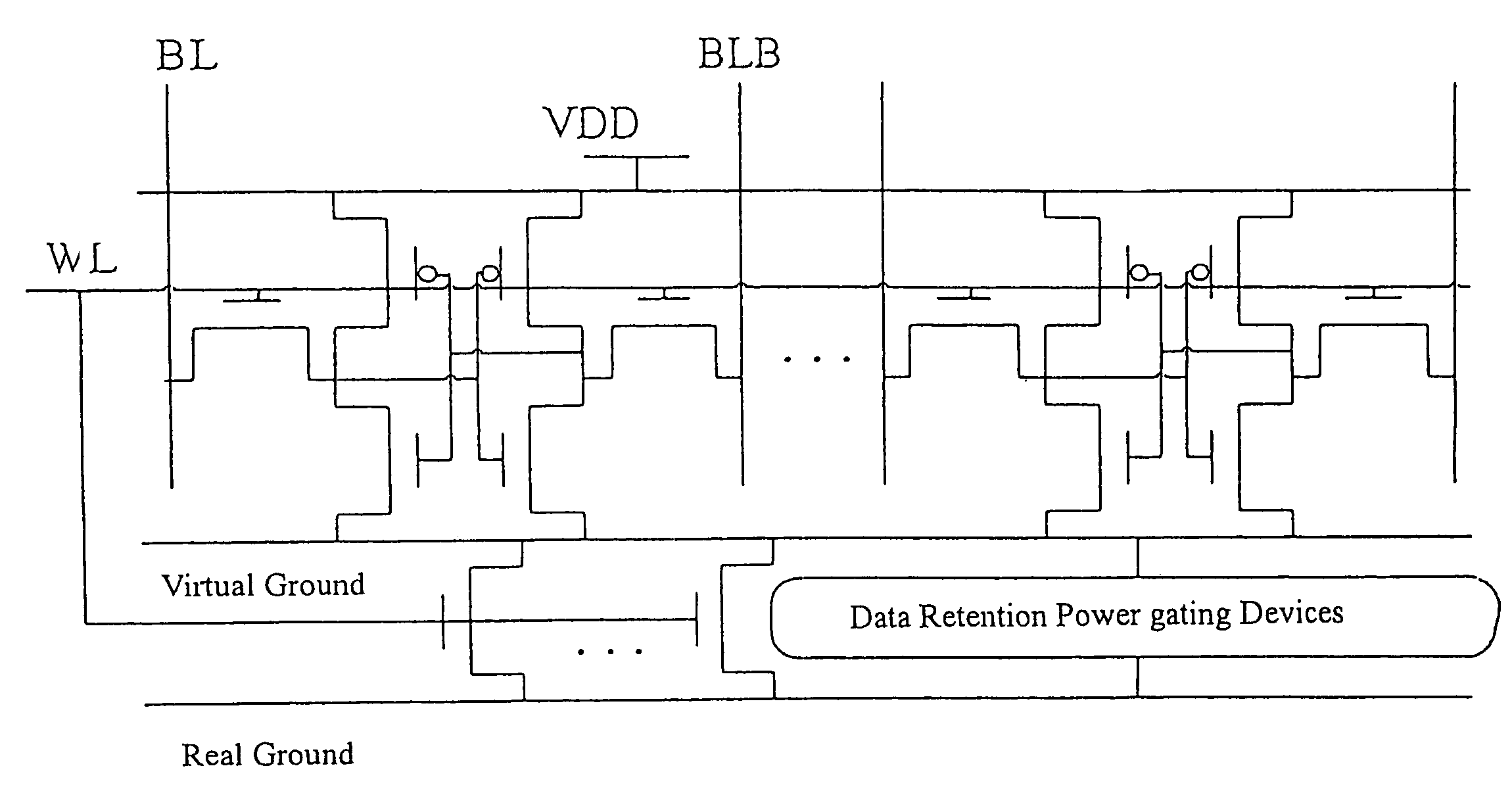
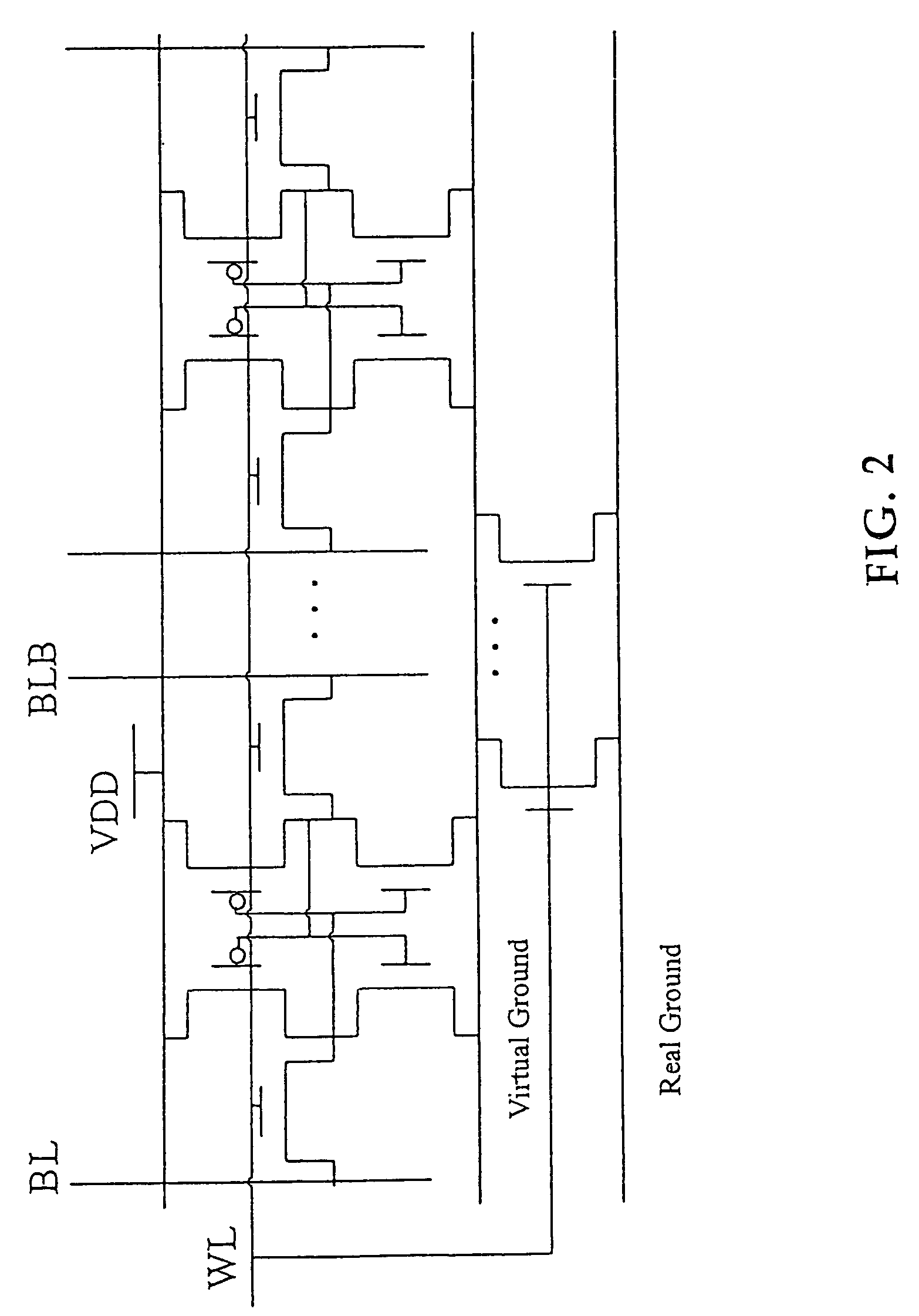
"The present invention proposes a new power gating structure that has data retention and intermediate modes, which are important for memory circuits. The power gating device has 4 operational modes: data retention, intermediate, active, and standby. The new structure helps to resolve problems such as data loss in standby mode, ground bounce, and power management complexity. It also reduces leakage current and standby power consumption. The invention provides a new power gating structure that can keep the ability of a conventional power gate in suppressing leakage current of advanced process formed circuits. The leakage current of the system-on-a-chip can be reduced without an additional manufacture process."

Problems solved by technology

Namely, when the prior power gating structure is in a standby mode-that is to say, when the power gating device is turned off, the data stored in an integrated circuit will be lost.
Therefore, the conventional power gating structure is not suitable for volatile memory circuits, such as latch / register file / SRAM.
Another conventional power gating device has the following problem: a ground bounce is induced at the switching of the power gating device, and if the power gating device is applied with a voltage source (VDD), a power supply bounce is encountered.

Method used


Image

  • Power gating structure having data retention and intermediate modes
  • Power gating structure having data retention and intermediate modes
  • Power gating structure having data retention and intermediate modes

Examples


Embodiment Construction

[0035]Referring to accompanying drawings, the features and inventiveness of the present invention are quite obvious. Cell stability determines soft-error and the sensitivity of a memory so as to deal with tolerances and operational conditions. FIG. 3(a) is a graph showing a static noise margin (SNM); FIG. 3(b) shows a step of measuring the static noise margin; and FIG. 4 shows a typical static noise margin simulation result. We can know from FIG. 4 that with the increase of the static noises, the data stored in the memory will gradually flip their states. After interposing all types of power gating device, we will use this method to test all static noise margins.

[0036]We appreciate from the above that the prior power gating device can operate normally in the combination circuit. However, during a standby mode, storage elements require a power gating device (named as a data retention power gating device) to maintain the static noise margin. This structure is shown in FIG. 5, wherein ...


PUM


Abstract

The present invention provides a power gating structure having data retention and intermediate modes and able to operate under multiple modes. A conventional power gating structure has only turn-on and turn-off functions, and is used to suppress a leakage current problem which has become more and more serious in advance manufacture processes, under a turn-off mode. However, in a memory circuit, such as latch, register and SRAM, when the power gate is turned off, a new power gating structure is required for data retention. The power gating structure of the present invention can be set into one of 4 different operational modes: a data retention mode for maintaining the static noise margin of the memory, an intermediate mode for reducing the interference on ground and power levels, an active mode used when the circuit operates in normal condition, and a standby mode used when the circuit does not operate.

Description

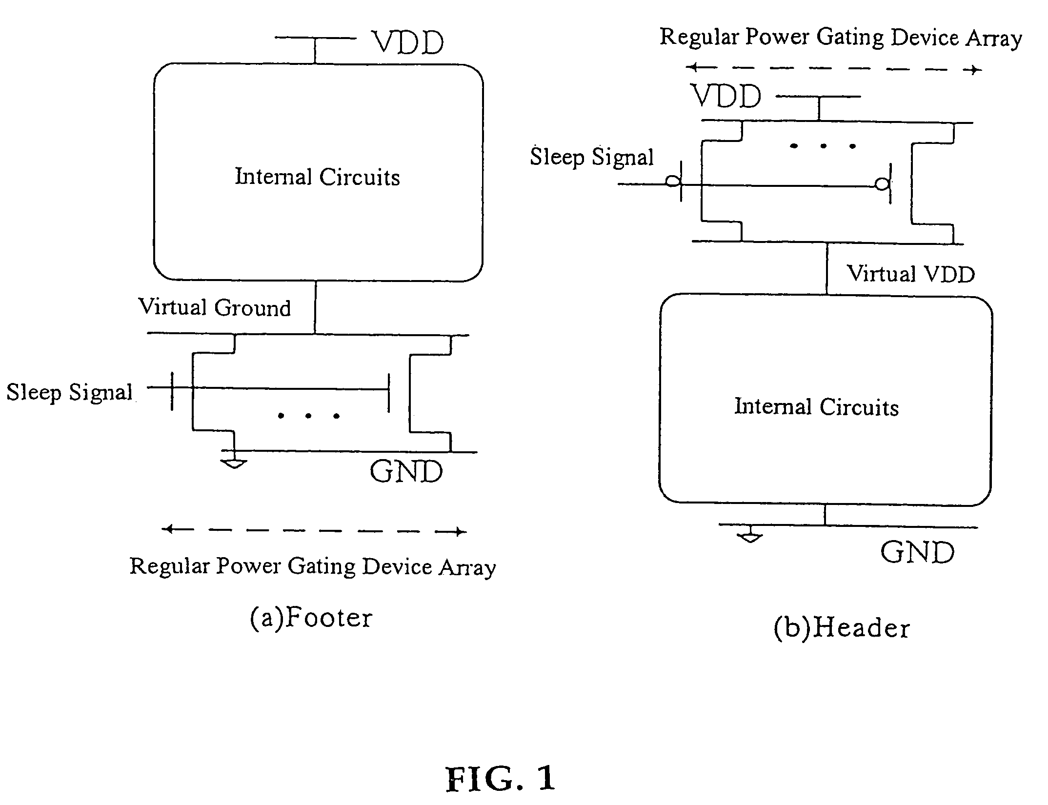
BACKGROUND OF THE INVENTION[0001]1. Field of the Invention[0002]The present invention relates to a new power-gating structure, and in particular to a power-gating structure in which the data stored in volatile memories can be maintained when the system is in a standby mode, and a ground or power supply bounce caused at the switching of a power-gating device can be reduced.[0003]2. Description of the Related Art[0004]As shown in FIG. 1, prior power gating (control) devices can be classified into two, i.e. a footer device and a header device. The footer device is to interpose NMOS sleep transistors between a real ground and a virtual ground; and the header device is to interpose PMOS sleep transistors between a real voltage source (real VDD) and a virtual voltage source (virtual VDD). Moreover, an individual internal circuit can be a combination circuit or a sequential circuit; and the power gating device can receive a sleep signal from a power management unit which determines a curre...

Claims


Application Information

Patent Timeline
Patent Type & Authority Patents(United States)
IPC IPC(8): H03K17/16
CPCH03K19/0016G11C11/413
Inventor HUA, CHUNG-HSIENHWANG, WEI
Owner NAT CHIAO TUNG UNIV
Learn More