EGR metallic high load diesel oxidation catalyst

a high-load, diesel technology, applied in the direction of machines/engines, mechanical equipment, non-fuel substance addition to fuel, etc., can solve the problems of affecting the cooling efficiency of the engine, the loss of needed cooling efficiency, and the impact of space constraints, so as to improve the operational efficiency, maintain efficiency, and high platinum group metals loading

Inactive Publication Date: 2007-11-27
INT ENGINE INTPROP CO LLC
View PDF7 Cites 39 Cited by
  • Summary
  • Abstract
  • Description
  • Claims
  • Application Information

AI Technical Summary

Benefits of technology

[0013]The metallic high load DOC comprises a low restriction metallic substrate, a metal foil for example, that allows desired maximum EGR rates to continue to be achieved. A preferred metallic high load DOC comprises a high platinum group metals (PGM) loading located before the EGR cooler. An advantage of the use of Platinum and Palladium is the ability of the DOC to maintain efficiency upon a return to lower temperature EGR flow after a period of high temperature EGR flow. High temperature EGR flow typically occurs when the engine runs at high engine load.
[0014]By placement of the metallic high load DOC in close physical proximity to an exhaust manifold, it is believed that the DOC can exhibit improved operational effectiveness in comparison to placement at other locations because of its exposure to manifold and engine heat. The inclusion of this DOC in the EGR loop, even when placed in close proximity to an exhaust manifold, should also have no significant impact on hydrocarbons (HC) that are intentionally created at certain times in engine exhaust for conveyance through a turbocharger to an underfloor DOC in a motor vehicle where they are burned to raise exhaust temperature to levels suitable for regenerating a diesel particulate filter (DPF) or catalyzed DPF further downstream in the exhaust system. The burning of increased amounts of HC in exhaust flow through the metallic high load DOC create a rise in EGR gas temperature. This higher temperature could aid in burning off deposits in the cooler due to the engine having been operating at lower loads characterized by lower exhaust gas temperature.

Problems solved by technology

Constraints on available space may also affect the geometry of an EGR cooler and the number of coolers that are needed in a loop to provide the maximum temperature drop.
However, because EGR cooler geometry doesn't change as engine operating conditions change, exhaust may at times be cooled to lower temperatures than it otherwise would if the EGR cooler were smaller.
It has been observed from actual engine testing that an EGR cooler sized to provide a certain outlet temperature at maximum heat rejection may lose cooling efficiency as accumulated engine running time increases.
Loss of needed cooling efficiency can have potentially unfavorable implications for an emission control strategy.
Furthermore, different engine operating conditions create varying degrees of unburned hydrocarbons and soot in engine exhaust.
Over time however, the running of the engine was found to cause sticky, soot-like material to be deposited on cooler surfaces.
For example, the cooler outlet became noticeably caked with such deposits.
The deposits can also occur on the EGR valve, potentially impairing its operation.

Method used


Image

  • EGR metallic high load diesel oxidation catalyst
  • EGR metallic high load diesel oxidation catalyst

Examples


Embodiment Construction

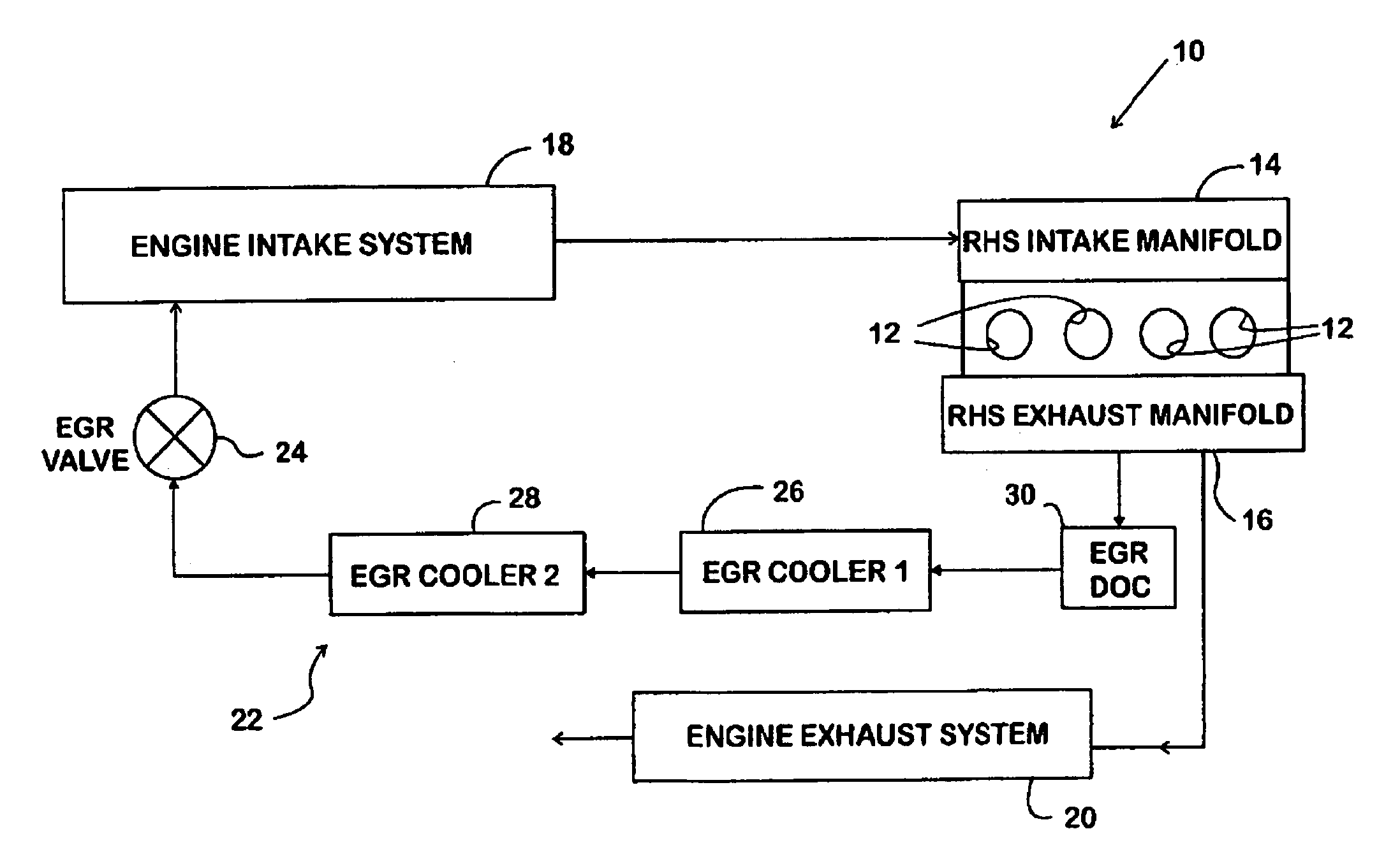
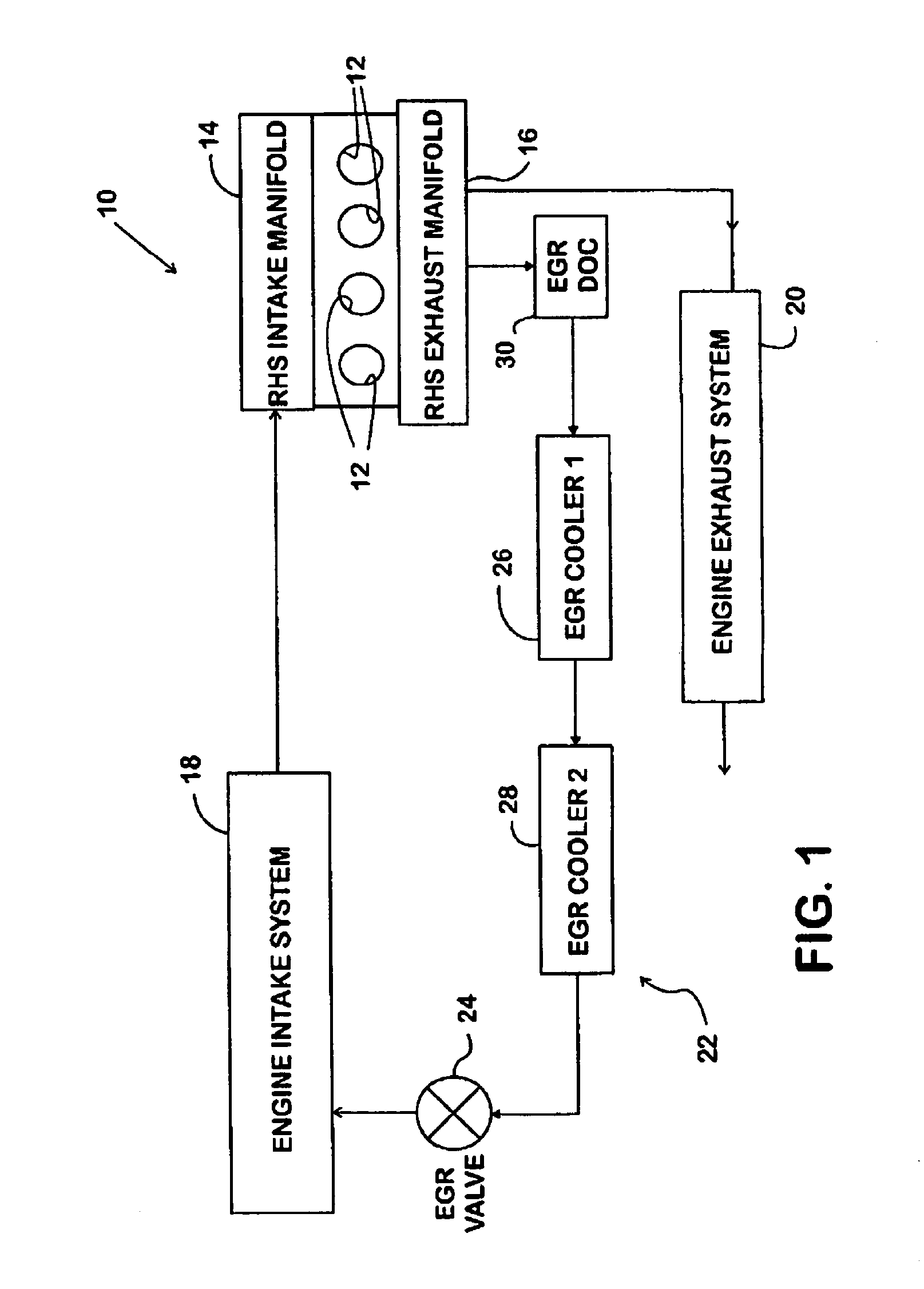
[0021]FIG. 1 shows schematically a portion of an exemplary turbocharged diesel engine 10 for powering a motor vehicle. Engine 10 comprises cylinders 12 within which pistons (not shown) reciprocate. Each piston is coupled to a respective throw of a crankshaft by a corresponding connecting rod (also not shown). A V-shape engine has two banks of cylinders, but only the right hand side bank is shown in the drawing. Associated with the bank is an intake manifold 14 and an exhaust manifold 16.

[0022]Engine 10 comprises an intake system 18 and an exhaust system 20. Turbocharging is provided by a turbocharger (not shown) having one or more turbines in exhaust system 20 that operate one or more compressors in intake system 18.

[0023]Engine 10 further comprises an exhaust gas recirculation (EGR) loop 22 between exhaust system 20 and intake system 18. EGR loop 22 provides high-pressure EGR by having an inlet communicated directly to cylinder exhaust through exhaust manifold 16 and an outlet that...


PUM


Abstract

A compression ignition engine (10) has an EGR loop (22) that contains a metallic DOC (30) for treating recirculated exhaust gas obtained directly from cylinder exhaust through an exhaust manifold (16) before the exhaust gas passes through a cooler (26, 28) and an EGR valve (24) to an intake system (18).

Description

FIELD OF THE INVENTION[0001]This invention relates to internal combustion engines, including particularly, compression ignition (i.e. diesel) engines. More specifically, the invention relates to improvements in EGR (exhaust gas recirculation) loops for maintaining effectiveness of EGR coolers in the loops.BACKGROUND OF THE INVENTION[0002]The use of EGR as an addition to charge air introduced into cylinders of an engine aids in controlling tailpipe emissions, especially NOx and particulates. A typical EGR loop has an inlet that is in communication with the engine exhaust system and an outlet that is in communication with the engine intake system. An EGR valve controls flow of exhaust gas through the loop from the exhaust system to the intake system.[0003]Depending on the pierce point of the EGR loop to the exhaust system, an EGR cooler may be included in the loop to cool the exhaust before it reaches the EGR valve. The EGR cooler size is a function of the maximum temperature drop tha...

Claims


Application Information

Patent Timeline
Patent Type & Authority Patents(United States)
IPC IPC(8): F02B47/10F02B47/08
CPCF02M25/0732F02M25/074Y02T10/121F02M26/24F02M26/35
Inventor TYO, MATTHEW A.ADELMAN, BRAD J.
Owner INT ENGINE INTPROP CO LLC
Why Eureka
Try Eureka