Image processing apparatus and method

a technology of image processing and image, applied in the field of image processing apparatus and method for coding or decoding images, can solve the problems of large, high cost, and incompatibility with a bit rate lower than mpeg1, and achieve the effect of high pixel precision and less cos

Inactive Publication Date: 2009-06-30
SONY CORP
View PDF15 Cites 42 Cited by
  • Summary
  • Abstract
  • Description
  • Claims
  • Application Information

AI Technical Summary

Benefits of technology

[0034]Accordingly, in view of the above background, it is an object of the present invention to provide a smaller, less expensive, lower-power image processing apparatus that can substantially maintain the coding efficiency, and to provide a method for use in such an image processing apparatus.
[0048]As described above, according to the present invention, it is possible to provide a smaller, less expensive, lower-power image processing apparatus that can perform motion prediction / compensation with high pixel precision, and also to provide a method for use in such an image processing apparatus.

Problems solved by technology

MPEG2 is mainly used for coding high quality images for broadcasting, and is not compatible with the coding amount (bit rate) lower than MPEG1, namely, it is not compatible with a higher compression ratio.
Accordingly, a large, expensive, and wide-band frame memory and a high-performance computation circuit are required, and power consumption is accordingly increased.
That is, a greater overhead is generated for a smaller MC block, causing a wider memory band.

Method used


Image

  • Image processing apparatus and method
  • Image processing apparatus and method
  • Image processing apparatus and method

Examples


first embodiment

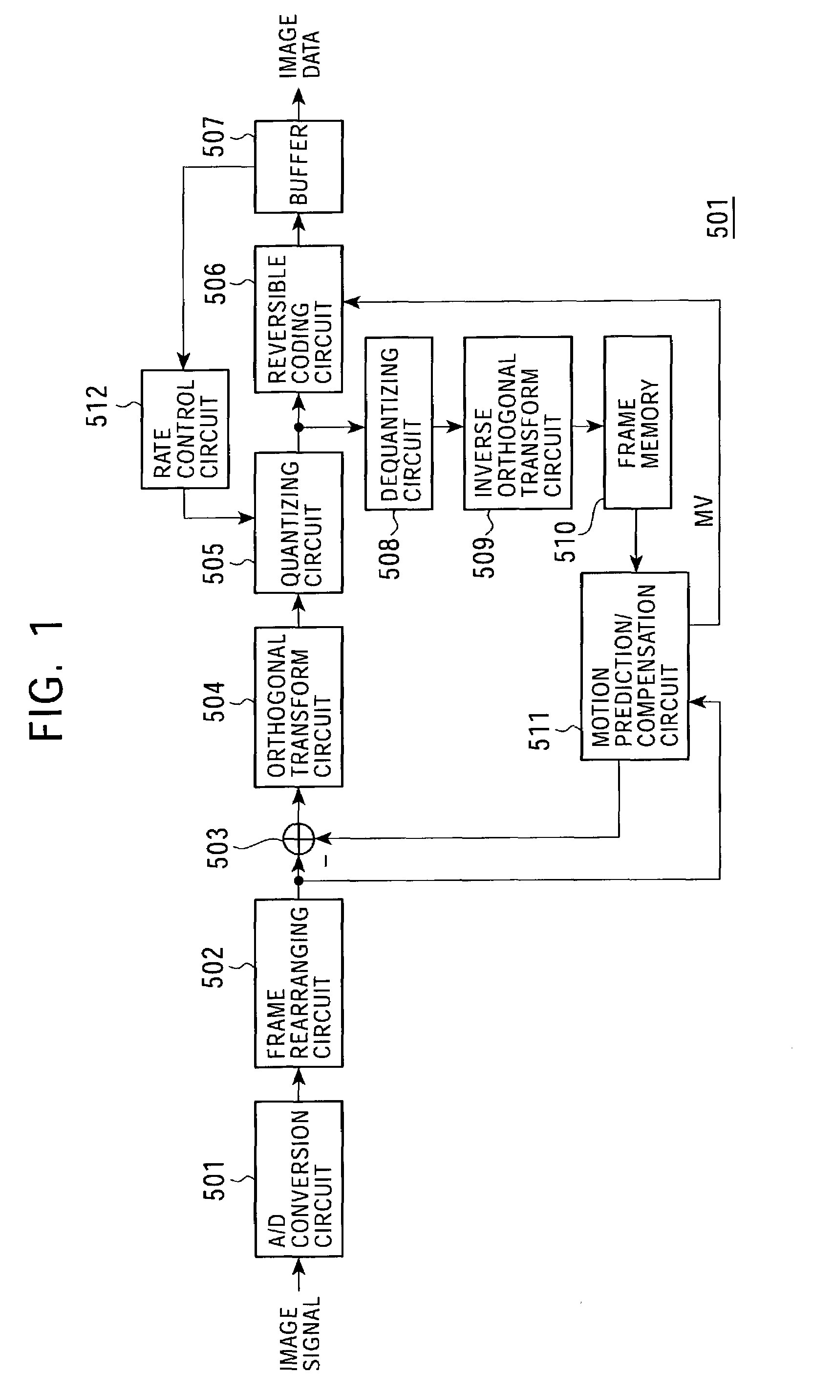
[0076]FIG. 5 is a schematic diagram illustrating a communication system 1 according to a first embodiment of the present invention. The communication system 1 includes, as shown in FIG. 5, a coding apparatus 2 disposed at a transmitter, and a decoding apparatus 3 disposed at a receiver.

[0077]In the coding apparatus 2, an image signal (bit stream) compressed by orthogonal transform, such as DCT or Karhunen-Loeve transform, and motion compensation, is generated. After being modulated, the image signal is transmitted via a transmission medium, such as a satellite broadcast wave, a cable television network, a telephone line network, or a cellular telephone line network.

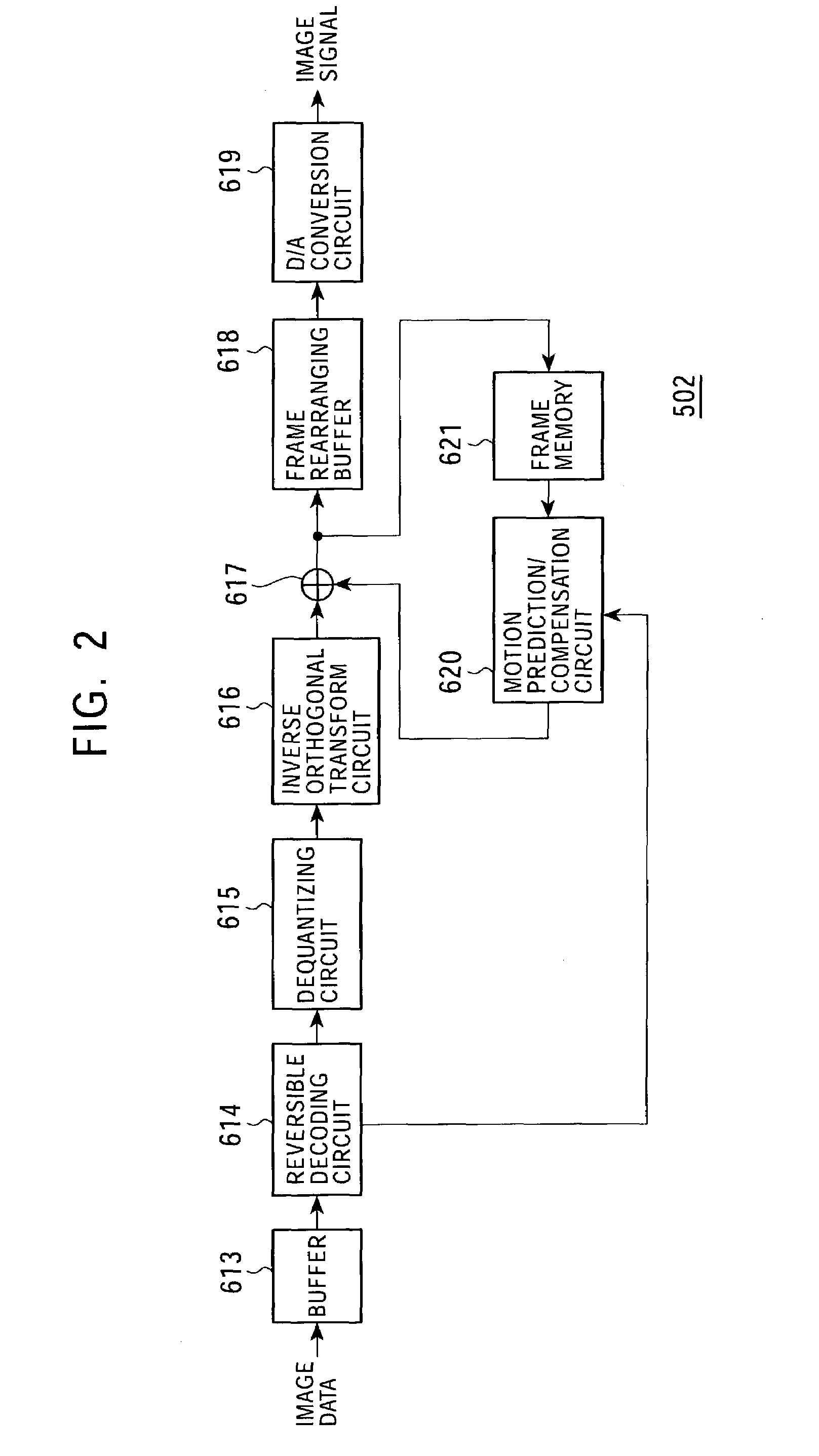
[0078]In the receiver, the received image signal is demodulated, and is decompressed by performing inverse orthogonal transform and motion compensation, which correspond to the orthogonal transform and motion compensation performed when the signal is modulated.

[0079]The above-described transmission medium may be a recordi...

second embodiment

[0194]In the above-described first embodiment, motion prediction / compensation is performed with 1 / 4 pixel precision in the coding apparatus 2 and the decoding apparatus 3. In the second embodiment, motion prediction / compensation is performed with 1 / 2 pixel precision in the coding apparatus 2 and the decoding apparatus 3.

[0195]In the second embodiment, the configurations and operations of the coding apparatus 2 and the decoding apparatus 3 are similar to those of the counterparts of the first embodiment, except for the processing performed in the interpolation computation circuit 45 shown in FIGS. 8 and 15.

[0196]In this embodiment, in the interpolation computation circuit 45, interpolation pixel signals S(b) at interpolation positions b corresponding to 1 / 2 pixel positions shown in FIGS. 11 and 12 contained in the image signal S44 are clipped with a range [0, 255], and from the clipped interpolation pixel signals S(b) and the pixel signals S(A) contained in the image signal S40 input...

third embodiment

[0198]In the third embodiment, motion prediction / compensation is performed with 1 / 8 pixel precision in the coding apparatus 2 and the decoding apparatus 3 shown in FIG. 1.

[0199]The communication system of the third embodiment is similar to that of the first embodiment, except for the configurations of a motion prediction / compensation circuit 135 of the coding apparatus 2 and a motion prediction / compensation circuit 181 of the decoding apparatus 3.

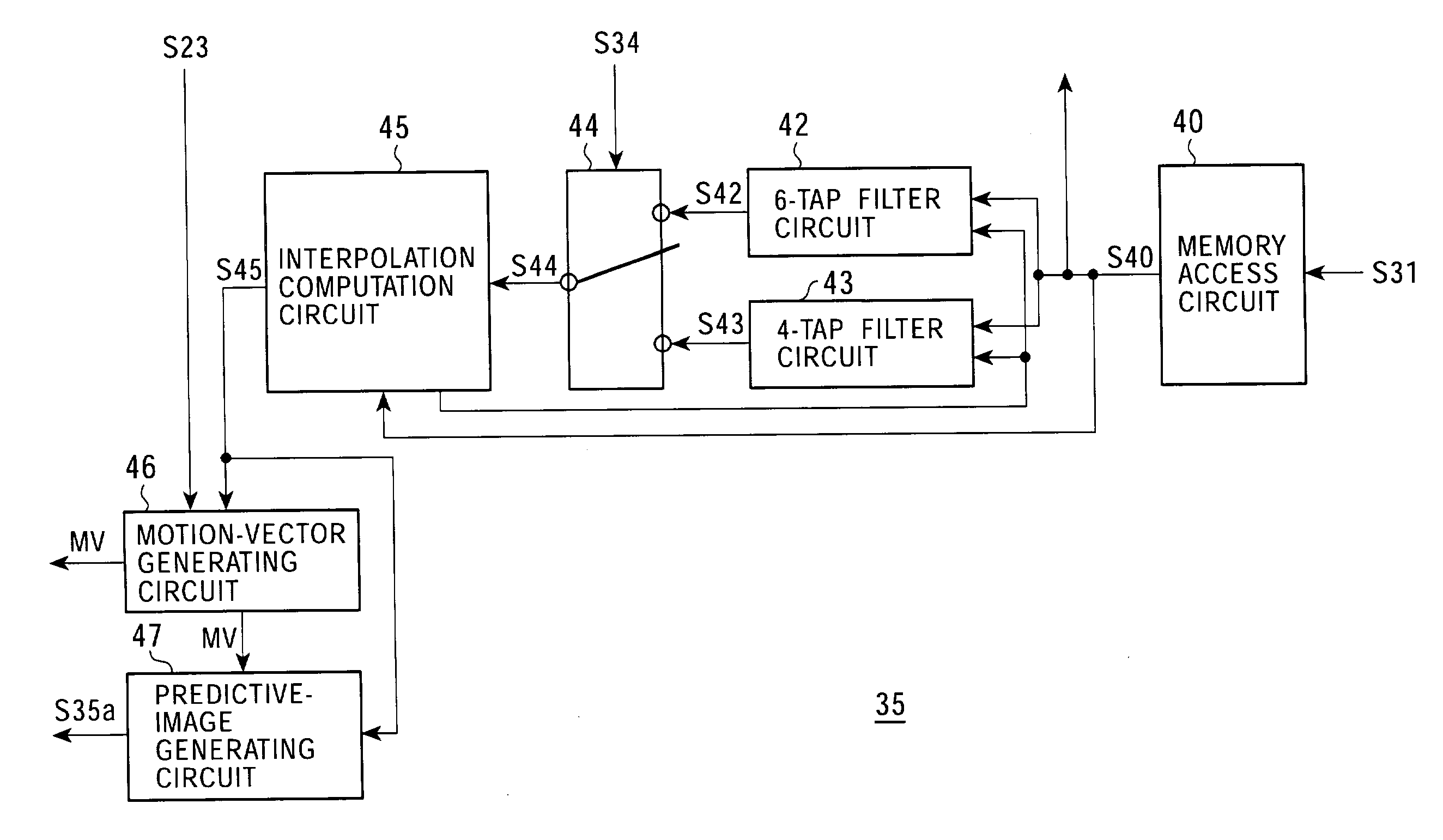
[0200]FIG. 16 is a functional block diagram illustrating the motion prediction / compensation circuit 135 of the coding apparatus 2.

[0201]The motion prediction / compensation circuit 135 includes, as shown in FIG. 16, a memory access circuit 40, an 8-tap filter circuit 142, a 6-tap filter circuit 143, a selection circuit 144, an interpolation computation circuit 145, a motion-vector generating circuit 46, and a predictive-image generating circuit 47.

[0202]In FIG. 16, the same elements as those shown in FIG. 8 are designated with like reference ...


PUM


Abstract

A 6-tap filter circuit and a 4-tap filter circuit generate interpolation pixel signals of an image signal S40. A selection circuit selects one of the 6-tap filter circuit and the 4-tap filter circuit based on a filter selection signal S34 according to the block size of a motion vector to be generated in a motion-vector generating circuit.

Description

BACKGROUND OF THE INVENTION[0001]1. Field of the Invention[0002]The present invention relates to an image processing apparatus and method for coding or decoding images.[0003]2. Description of the Related Art[0004]For transmitting and storing information with high efficiency, apparatuses for digital-compressing image data according to orthogonal transform, such as discrete cosine transform (DCT), and motion compensation, in compliance with Moving Picture Experts Group (MPEG), by utilizing the redundancy unique to image information are becoming widespread in information transmitters in, for example, broadcast stations and information receivers in, for example, households.[0005]In particular, MPEG2(ISO / IEC13818-2) is defined as a general-purpose image coding method, and is currently used in widely available applications, such as in professional applications and consumer applications, by covering interlaced scanning images, sequential scanning images, standard resolution images, and hig...

Claims


Application Information

Patent Timeline
Patent Type & Authority Patents(United States)
IPC IPC(8): H04B1/66H04N19/50H04N19/105H04N19/117H04N19/132H04N19/136H04N19/139H04N19/157H04N19/176H04N19/40H04N19/423H04N19/426H04N19/503H04N19/51H04N19/523H04N19/59H04N19/593H04N19/61H04N19/625H04N19/80H04N19/91
CPCH04N19/176H04N19/61H04N19/117H04N19/157H04N19/523
Inventor SATO, KAZUSHISUZUKI, TERUHIKOTAKAHASHI, KUNIAKIYAGASAKI, YOICHI
Owner SONY CORP
Why Eureka
Try Eureka