Organic electroluminescent display device

a technology of electroluminescent display and organic el, which is applied in the direction of discharge tube luminescnet screen, discharge tube/lamp details, electric discharge lamps, etc., can solve the problems of easy degradation of organic film which constitutes the light emitting layer, and is not possible to incorporate a sufficient quantity of desiccant in the inside of the sealed space, so as to suppress the degradation of organic light emitting layer, high heat resistance, and high chemical resistance

Active Publication Date: 2007-08-23
SAMSUNG DISPLAY CO LTD +1
View PDF10 Cites 40 Cited by
  • Summary
  • Abstract
  • Description
  • Claims
  • Application Information

AI Technical Summary

Benefits of technology

[0016]Accordingly, it is an object of the present invention to provide an organic EL display device which can maintain a light emission efficiency thereof and can possess a prolonged lifetime thereof by suppressing the degradation attributed to moisture of a multi-layered organic light emitting layer which includes such sealing structure.
[0027]Due to the respective means of the present invention, there is no possibility that a gas which is separated from a desiccant layer or a gas which is diffused in the desiccant layer after intruding from an end portion of a sealing layer reaches the organic light emitting layer thus suppressing the degradation of the organic light emitting layer. Since the material which exhibits high heat resistance and high chemical resistance can be used for forming the moisture prevention layer, the freedom in the selection of the desiccant can be increased. Further, it is possible to seal using the resin film and hence, it is possible to provide the display device which is light-weighted and thin and which exhibits high reliability and a prolonged lifetime.

Problems solved by technology

Such an organic EL display device has a drawback that an organic film which constitutes the light emitting layer is easily degraded due to moisture.
When the desiccant is provided only to the outer periphery of the organic light emitting layer in patent document 2, a position at which the desiccant is arranged is limited and hence, it is not possible to incorporate a sufficient quantity of desiccant in the inside of the sealed space.

Method used


Image

  • Organic electroluminescent display device
  • Organic electroluminescent display device
  • Organic electroluminescent display device

Examples


embodiment 1

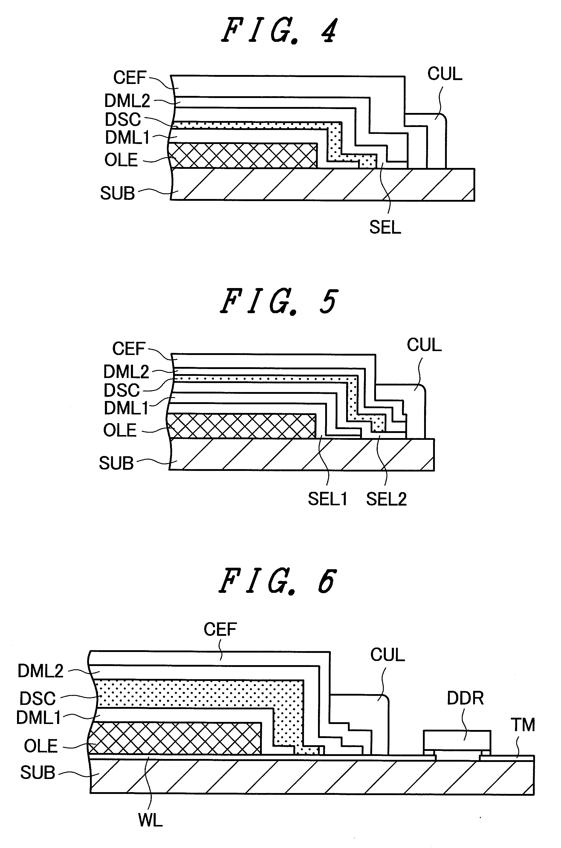
[0041]FIG. 4 is a cross-sectional view of an essential part for explaining the structure of an embodiment 1 of the organic EL display device according to the present invention. The basic structure of the organic EL display device is substantially equal to the corresponding structure of the organic EL display device shown in FIG. 3. In the embodiment 1, on the light emitting layer OLE, the first moisture prevention layer DML1 and the moisture absorption layer DSC which are stacked on the main surface of the TFT substrate SUB, an adhesive layer SEL is formed. That is, in the embodiment 1, the adhesive layer SEL is formed between the moisture absorption layer DSC and the second moisture prevention layer DML2, wherein the adhesive layer SEL fixedly mounts the first moisture prevention layer DML1 and the moisture absorption layer DSC to the main surface of the TFT substrate SUB together with the second moisture prevention layer DML2.

[0042]The first moisture prevention layer DML1 is made ...

embodiment 2

[0043]FIG. 5 is a cross-sectional view of an essential part for explaining the structure of an embodiment 2 of the organic EL display device according to the present invention. The basic structure of the organic EL display device is substantially equal to the corresponding structure of the organic EL display device shown in FIG. 3. In the embodiment 2, a first adhesive layer SELL is arranged between the light emitting layer OLE and the first moisture prevention layer DML1 which are stacked on the main surface of the TFT substrate SUB, and a second adhesive layer SEL2 is arranged between the first moisture prevention layer DML1 and the moisture absorption layer DSC. In the embodiment 2, wherein these adhesive layers SEL1, SEL2 fixedly mount the first moisture prevention layer DML1, the moisture absorption layer DSC and the second moisture prevention layer DML2 to the main surface of the TFT substrate SUB.

[0044]The first moisture prevention layer DML1 is formed of an aluminum foil (Al...


PUM


Abstract

The present invention provides an organic EL display device which can maintain a light emitting efficiency and can prolong a lifetime by suppressing the degradation of an organic light emitting layer attributed to moisture. The organic EL display device includes a sealing film formed of an organic film which covers an organic light emitting layer which is constituted of a first electrode which is formed on a main surface of an insulation substrate, an organic EL layer of the multi-layered structure, and a second electrode and has a peripheral end portion sealed to a peripheral portion of the insulation substrate. The organic EL display device includes a moisture-resistant structural body which covers an upper surface and a side surface of the organic light emitting layer and is formed by stacking a first moisture prevention layer, a moisture absorption layer and a second moisture prevention layer in this order. The first moisture prevention layer, the moisture absorption layer and the second moisture prevention layer on the side surface of the organic light emitting layer are bent toward the side surface from the upper surface of the organic light emitting layer and, further, are bent parallel to a main surface of the insulation substrate from the side surface, and lower surfaces of the respective bent portions are hermetically adhered to the main surface of the substrate.

Description

CROSS-REFERENCE TO RELATED APPLICATIONS[0001]The disclosure of Japanese Patent Application No. 2006-042275 filed on Feb. 20, 2006 (yyyy / mm / dd) including the claims, the specification, the drawings and the abstract is incorporated herein by reference in its entirety.BACKGROUND [0002]1. Field of the Invention[0003]The present invention relates to an organic EL display device, and more particularly to a technique which is effectively applicable to an organic EL display device which can prolong a lifetime thereof and can enhance reliability thereof by suppressing the degradation of an organic EL layer attributed to moisture.[0004]2. Description of the Related Art[0005]As a flat-panel-type display device, a liquid crystal display device (LCD), a plasma display device (PDL), a field emission type display device (FED), an organic EL display device (OLED) and the like have been put into practice or have been studied for future practical use. Among these display devices, the organic EL displ...

Claims


Application Information

Patent Timeline
Patent Type & Authority Applications(United States)
IPC IPC(8): H05B33/04H01L51/50
CPCH01L51/5237H10K50/8426H10K50/846H10K50/844H05B33/04
Inventor MATSUURA, TOSHIYUKITANAKA, MASAHIRO
Owner SAMSUNG DISPLAY CO LTD
Why Eureka
Try Eureka