Remote control system, remote commander and remote control method, apparatus to be remotely controlled, and computer system

a remote control and computer system technology, applied in the field of remote control systems, can solve problems such as the directivity of the communication method using infrared rays, the inability to establish communication, and the inability to receive a reply from the transmitter

Inactive Publication Date: 2006-11-09
SATURN LICENSING LLC
View PDF5 Cites 50 Cited by
  • Summary
  • Abstract
  • Description
  • Claims
  • Application Information

AI Technical Summary

Benefits of technology

[0014] It is desirable to provide an excellent remote control system, remote commander and remote control method, apparatus to be remotely controlled, and computer system that enable interactive communication between the remote commander and an apparatus to be operated using an IP network.
[0015] It is further desirable to provide an excellent remote control system, remote commander and remote control method, apparatus to be remotely controlled, and computer system that enable a user to perform a remote control operation upon an apparatus in front of him or her, the apparatus having been selected so as to be operated from among a plurality of apparatuses freed from constraints of directivity and communication range.
[0016] It is still further desirable to provide an excellent remote control system, remote commander and remote control method, apparatus to be remotely controlled, and computer system that enable a user to easily specify a desired apparatus to be controlled and then perform a remote control operation upon the specified apparatus when a plurality of controllable apparatuses exist on a network.
[0019] When network-ready AV apparatuses are connected to each other, a user can seamlessly use these AV apparatuses on a home network. As more and more AV apparatuses are supported so as to become network-ready apparatuses, a remote control operation using an IP network that has few constraints of directivity and communication range can be performed. An IP remote controller used in such a remote control operation is configured to interactively communicate with an AV apparatus to be operated. Therefore, according to the IP remote controller, the following effects can be achieved: the enablement of reliable communication by performing transmission confirmation; capability of handling of a complicated command system by adopting a GUI operation; and capability of transmission of very large amounts of data intended for, for example, streaming distribution of moving images, by using a relatively wide band.
[0029] Upon receiving the command, an apparatus to be remotely controlled displays its user-friendly default or user-set name on a screen thereof as an operation. According to the above-described process, a user can compare the apparatus name that he or she has selected on the GUI selection screen to the apparatus name displayed on the screen of the actually specified apparatus to be remotely controlled on the basis of the contents of both screens. In particular, when the user-set name that is easier to understand for users is used, the display of the user-set name is more acceptable and understandable for users compared with the reaction of LED indication or beep sound generation.

Problems solved by technology

However, the communication method using infrared rays has a problem of directivity.
When the light receiving portion of a receiver is not directed in the range of a viewing angle of a transmitter, communication cannot be established.
Since the infrared communication method basically is a one-way communication method, a transmitter cannot receive a reply from a receiver, namely, cannot confirm the result of the transmission.
In the case of an infrared remote controller, when an apparatus to be controlled is not directed in the range of a viewing angle of the infrared remote controller, the apparatus cannot be operated owing to the constraint of directivity.
However, it cannot be determined whether the apparatus displayed on the GUI is truly the apparatus that a user wants to control at this time.
However, when all apparatuses on the network are listed on the selection screen, it is difficult for the user to specify the apparatus in front of him or her.

Method used


Image

  • Remote control system, remote commander and remote control method, apparatus to be remotely controlled, and computer system
  • Remote control system, remote commander and remote control method, apparatus to be remotely controlled, and computer system
  • Remote control system, remote commander and remote control method, apparatus to be remotely controlled, and computer system

Examples


Embodiment Construction

[0042] An embodiment of the present invention will be described in detail with reference to the accompanying drawings.

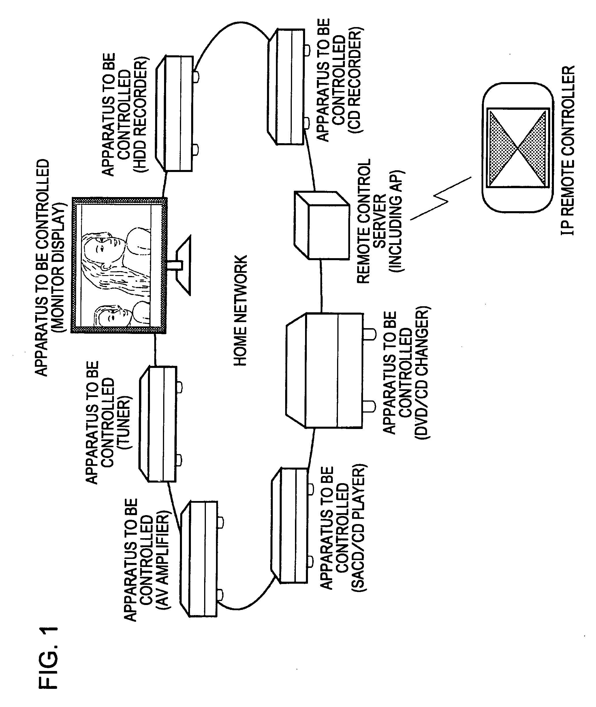
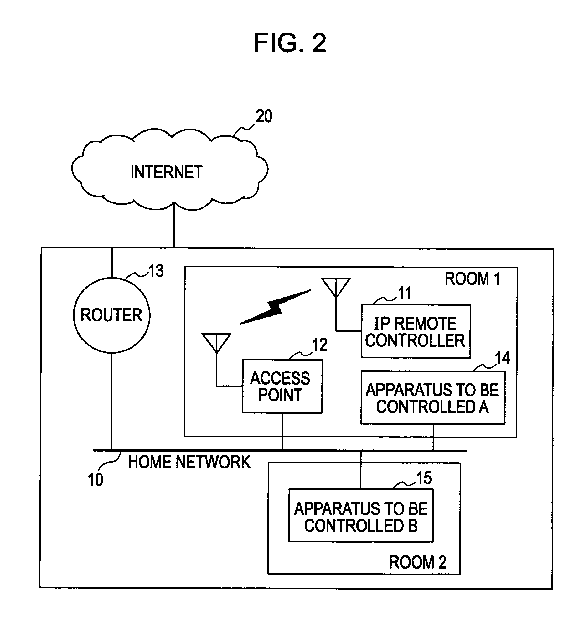
[0043]FIG. 1 is a schematic diagram of an exemplary home network to which an embodiment of the present invention is applied.

[0044] In the home network shown in the drawing, a remote control system is provided where a remote commander, i.e., IP remote controller, that uses an IP network instead of (or in addition to) an infrared transmission line is used.

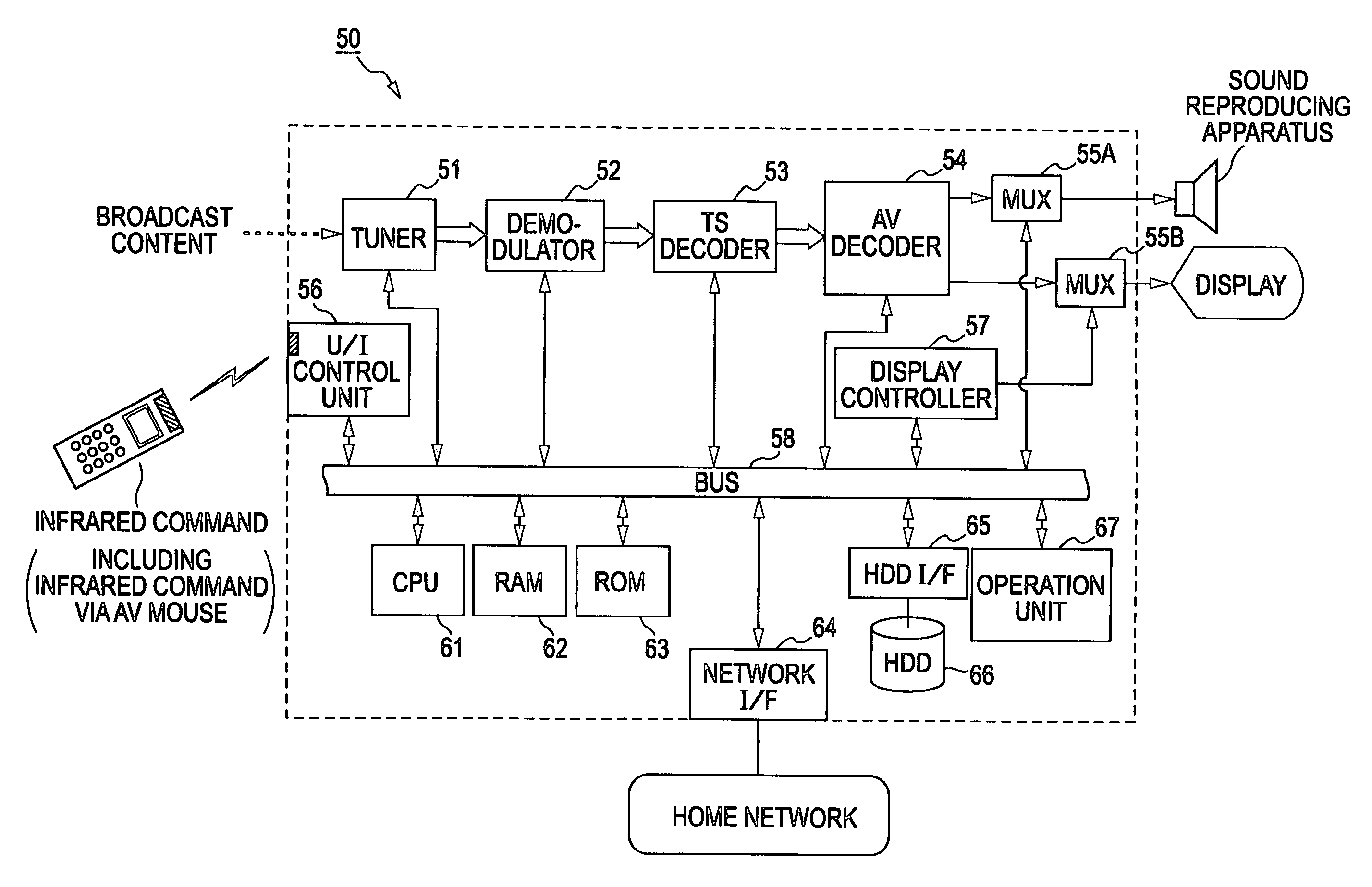
[0045] Apparatuses to be controlled by the IP remote controller are, for example, as follows: a content playback apparatus such as a monitor display for playing back AV contents or a sound reproducing apparatus (an AV amplifier); a content providing apparatus such as a tuner for receiving broadcast contents and providing the received broadcast contents on a home network or a CD / DVD player for providing contents stored in a medium; and a content recording apparatus for recording externally obtained contents such as ...


PUM


Abstract

When apparatuses controllable via a network exist inside and outside a user's visual range, a user remotely controls at least one of the apparatuses via the network using a predetermined control point in a remote control system. The remote control system includes the following: a mechanism that causes the control point to transmit a command for specifying an apparatus to be controlled via the network to an apparatus to be specified in accordance with a user's apparatus specifying operation; and a mechanism that causes the apparatus that has received the command for specifying an apparatus to be controlled to transmit a response via the network to the control point as well as to perform an operation using a device attached to the body of the apparatus in response to the command.

Description

CROSS REFERENCES TO RELATED APPLICATIONS [0001] The present invention contains subject matter related to Japanese Patent Applications JP 2005-135656 and 2006-004130 filed in the Japanese Patent Office on May 9, 2005 and Jan. 11, 2006, respectively, the entire contents of which are incorporated herein by reference. BACKGROUND OF THE INVENTION [0002] 1. Field of the Invention [0003] The present invention relates to remote control systems, remote commanders and remote control methods, apparatuses to be remotely controlled, and computer systems for remotely controlling television receivers, DVD players, other various AV and CE apparatuses, information apparatuses, etc. using the remote commanders. In particular, the present invention relates to remote control systems, remote commanders and remote control methods, apparatuses to be remotely controlled, and computer systems for achieving remote control freed from the constraints of directivity and transmittable distance from the remote co...

Claims


Application Information

Patent Timeline
Patent Type & Authority Applications(United States)
IPC IPC(8): H04L12/66G06F13/00H04N5/00H04Q9/00
CPCH04L2012/2849H04L12/282
Inventor OTSU, SHUICHINAKAMURA, JUNICHISATO, HIDEKI
Owner SATURN LICENSING LLC
Why Eureka
Try Eureka