

Metal burner membrane
- Summary
- Abstract
- Description
- Claims
- Application Information
AI Technical Summary
Benefits of technology
Problems solved by technology
Method used
Image

Examples
Embodiment Construction
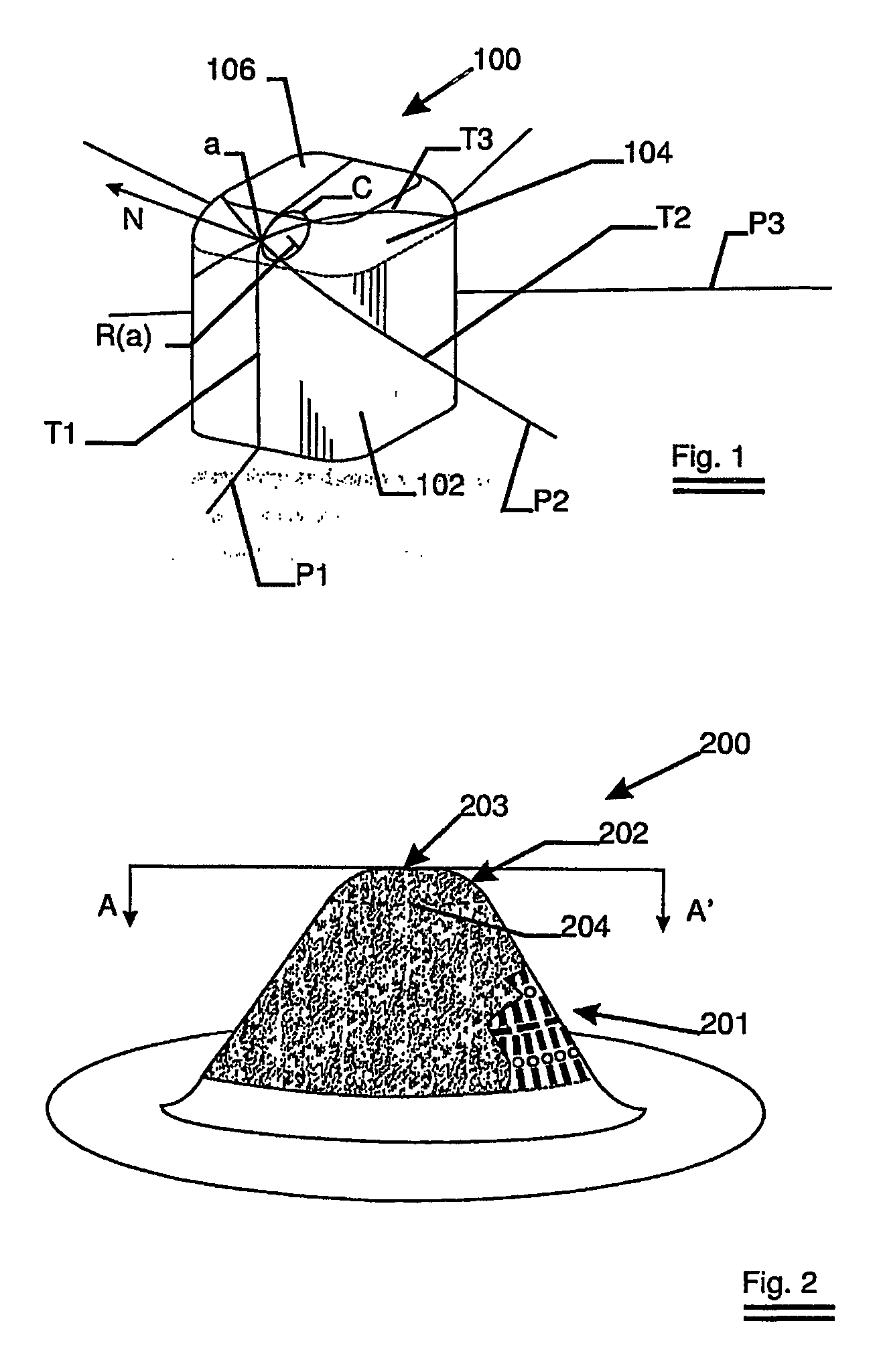
[0045] The basic geometrical features of the invention are illustrated in FIG. 1 where a shape 100 of a burner membrane is depicted consisting out of a base section 102, a transition section 104 and a top section 106. Take ‘a’ as point under consideration ‘a’ has its normal N to the surface. The planes P1, P2 and P3, all containing the normal N, cut the surface of the burner along different trajectories T1, T2 and T3 respectively. The osculating circle C touches T1 in ‘a’. If will be clear that of all planes containing N, the plane P1 determines the trajectory T1 with the smallest radius of curvature R(a) at ‘a’. If now for every point Y (not indicated on FIG. 1) of the transition section this R(x) is determined, the smallest value of all R(x)'s can be chosen. When the procedure is applied to the base section 102 a smallest radius of curvature ‘Rbase’ is obtained. Similarly, a smallest radius of curvature ‘rtransition’ can be found for the transition region. It is essential to the i...
PUM
 Abstract
Description
Claims
Application Information