Emesis basin

a technology of emesis and basin, which is applied in the direction of spittle receiving devices, washstands, domestic applications, etc., can solve the problems of fluid overflowing or splashing up and over the rear wall, affecting the safety of patients and caregivers, and reducing the potential for accidental spillage. , to achieve the effect of preventing accidental spillage and reducing the potential for spillag

Inactive Publication Date: 2006-11-16
BUERMANN HENRY
View PDF4 Cites 6 Cited by
  • Summary
  • Abstract
  • Description
  • Claims
  • Application Information

AI Technical Summary

Benefits of technology

[0011] The instant invention is an emesis basin having an upwardly extended rear wall which is preferably higher than the front and side walls. For the first time, the emesis basin includes the means to prevent accidental spillage, splashing or overflow, and therefore both reduces the perception that if the basin is used it will result in fluids being deposited back onto the user or onto the caregiver, and in actuality reduces the potential for that spillage by incorporating an upwardly extended rear wall which tends to prevent the overflow or spillage of said fluids in the direction which the propulsive force of the person depositing the fluids is generally aimed.

Problems solved by technology

While the concept of the emesis basin is generally known, it has also been known that both patients and caregivers are frequently hesitant to use the article.
Unfortunately, many of the people who will do this are those who under no circumstances should be doing so.
They may be weak or groggy, and as a consequence fall and incur additional injuries.
Doctors, nurses, and other caregivers have learned through experience that the propulsive force with which vomit strikes the bottom and rear wall of the emesis basin will in fact often result in the ejected fluid overflowing or splashing up and over the rear wall.
This is undesirable too, as the patient often is so concentrated on the action of vomiting or spitting that they are unable to satisfactorily control the emesis basin during the act of regurgitating, and frequently end up spilling the contents of the basin onto themselves.

Method used


Image

  • Emesis basin
  • Emesis basin
  • Emesis basin

Examples


Embodiment Construction

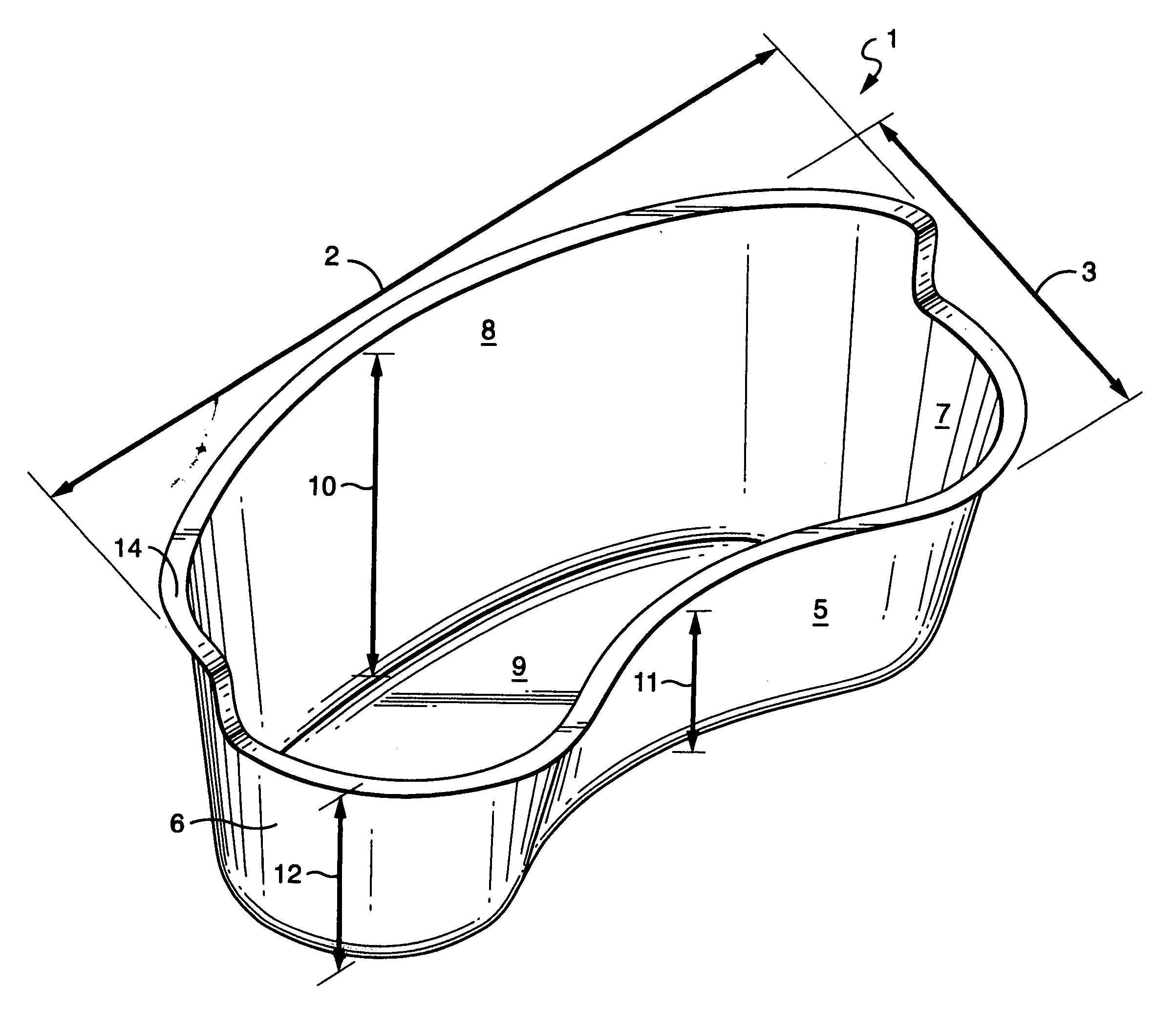
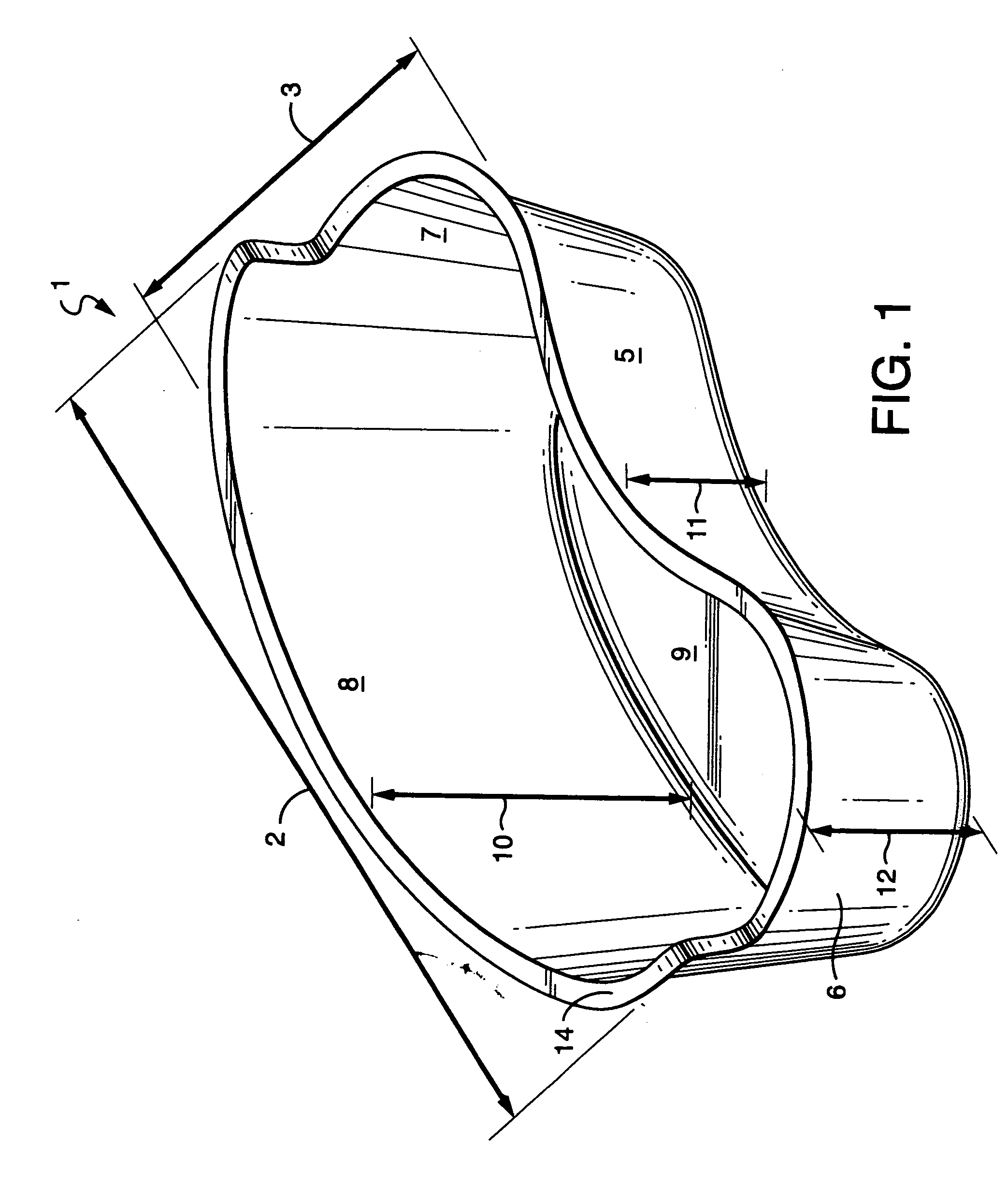
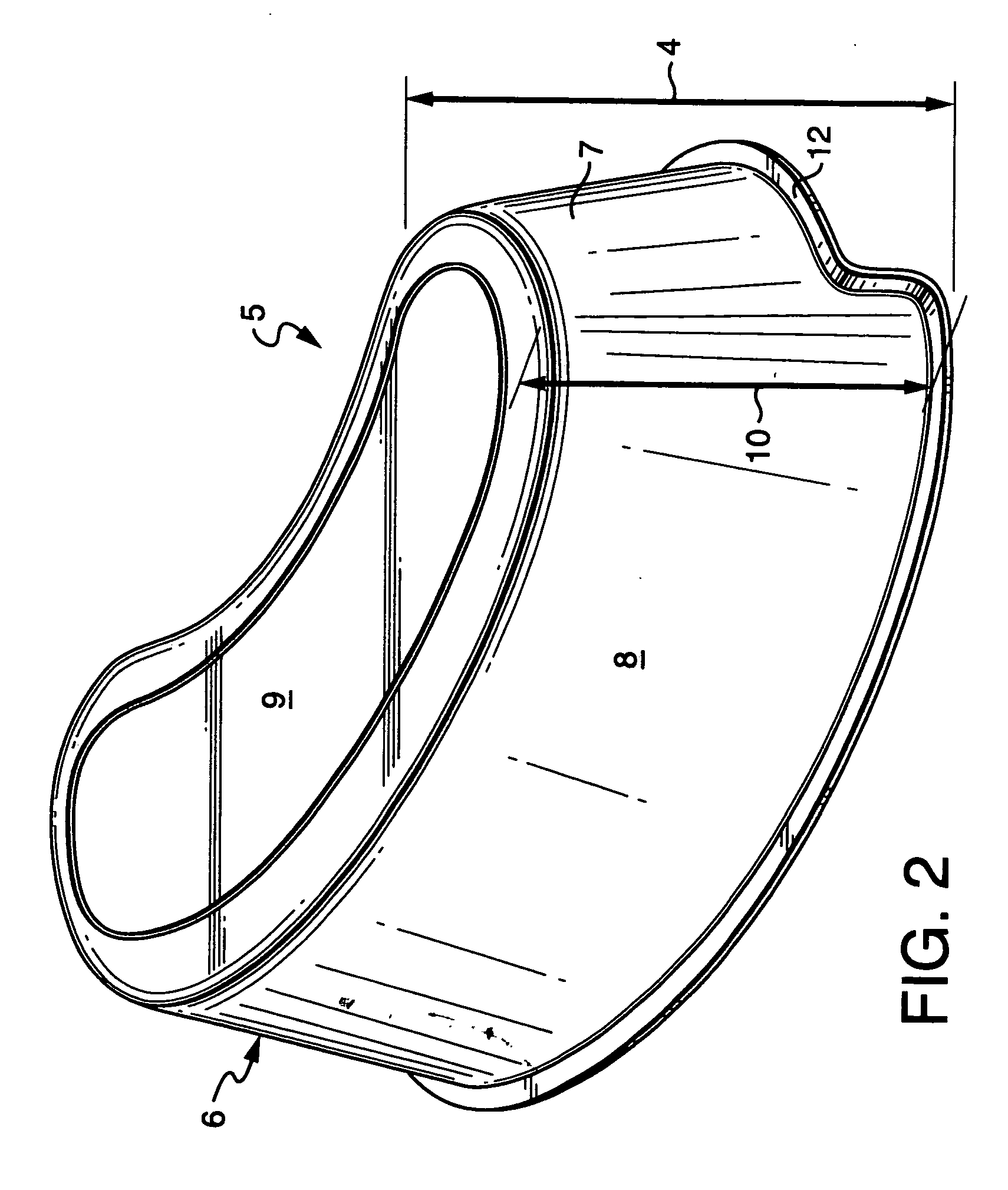
[0019] As per FIGS. 1 and 2, in the preferred embodiment an emesis basin (1) is generally “kidney” shaped. This overall form of the basin is well known and accepted throughout the medical instruments art field.

[0020] As per FIGS. 1 and 2, the emesis basin has length (2), width (3) and height (4). The emesis basin may further be generally understood to have an upwardly extending front wall (5), an upwardly extending left side wall (6) an upwardly extending right side wall (7), an upwardly extending rear wall (8) and a bottom (9). Obviously the top of the container is open, allowing for fluids to be deposited within the open interior space defined by the front wall, the left side wall, the right side wall, the rear wall and the bottom.

[0021] As has been noted, the emesis basin is kidney shaped, however that is not a requirement, it is simply a convention of the art field, and could be varied without departing from the scope of the claims.

[0022] Those who practice in the medical dev...


PUM


Abstract

An emesis basin for containing fluids comprising a front wall, a left side wall, a right side wall, a rear wall a bottom and an open top, each of the walls having height, and the rear wall height being greater than the front wall height.

Description

CROSS REFERENCE TO OTHER APPLICATIONS [0001] This is the first submission of an application for this article of manufacture. There are no other applications, provisional or non provisional. FEDERALLY SPONSORED RESEARCH AND DEVELOPMENT [0002] There are no federally sponsored or funded research or development projects or undertakings in any way associated with the instant invention. BACKGROUND OF THE INVENTION [0003] 1. Field of the Invention [0004] The instant invention relates to that field of devices consisting of articles of manufacture known as basins and bowls. Specifically, the instant invention is an improved emesis basin for receiving fluids and preventing accidental spillage. [0005] 2. Background Information [0006] The prior art known to the Inventor discloses that the emesis basin is known within the art of medical devices. These basins are most frequently used in hospital and similar settings, to receive fluids and contain those fluids until they are disposed of. As the na...

Claims


Application Information

Patent Timeline
Patent Type & Authority Applications(United States)
IPC IPC(8): A61J19/00A47K1/04
CPCA61J19/00
Inventor BUERMANN, HENRY
Owner BUERMANN HENRY
Why Eureka
Try Eureka