Bedpan

a bedpan and metal technology, applied in the field of bedpans, can solve the problems of inconvenient use, high cost of metal bedpans, and numerous disadvantages of metal bedpans compared to plastic bedpans,

Active Publication Date: 2006-11-16
MEDLINE IND LP
View PDF22 Cites 16 Cited by
  • Summary
  • Abstract
  • Description
  • Claims
  • Application Information

AI Technical Summary

Benefits of technology

[0015] In another aspect of the present invention, a bedpan for collecting waste includes a main body and a living hinge. The main body collects liquid waste and solid waste and includes a seating area and two cavities. The two cavities, which include a first cavity and a second cavity, are formed within the seating area. The first cavity receives the liquid waste and the second cavity receives the solid waste. The living hinge is rotatably connected to the main body for rotating between a closed position and an open position. The living hinge protects a user from splashing in the closed position and allows stacking of the bedpan in the open position.
[0016] In an alternative aspect of the present invention, a stackable bedpan for collecting waste includes a main body for collecting liquid waste and solid waste and a living hinge that is rotatably connected to the main body. The main body is made from a translucent thermoplastic material and includes a pl

Problems solved by technology

Metal bedpans, however, include numerous disadvantages in comparison to plastic bedpans.
For example, metal bedpans are expensive to manufacture, are uncomfortable to use, and are difficult to clean.
Metal bedpans are uncomfortable because they are cold and hard to the touch of a user.
Current plastic bedpans include numerous problems.
Some current bedpans cannot be used for both liquid and solid waste.
While some current bedpans can receive both liquid and solid waste, these bedpans are impractical because the liquid and solid waste are received in a single compartment.
One problem associated with these bedpans is that the attendant must pour the liquid waste into a graduated cylinder without also pouring the solid waste.
Another problem associated with these bedpans is that the attendant must use an additional container, e.g., the graduated cylinder, to measure the liquid waste.
However, the cushioning device includes corners that may cause discomfort during use.
Further, the cushioning device may be improperly attached to the bedpan, resulting in improper use of the bedpan, and may absorb liquid waste, resulting in wetting the user and, consequently, leading to ulcer formation.
Another problem associated with some bedpans is that they do not include both

Method used


Image

  • Bedpan
  • Bedpan
  • Bedpan

Examples


Embodiment Construction

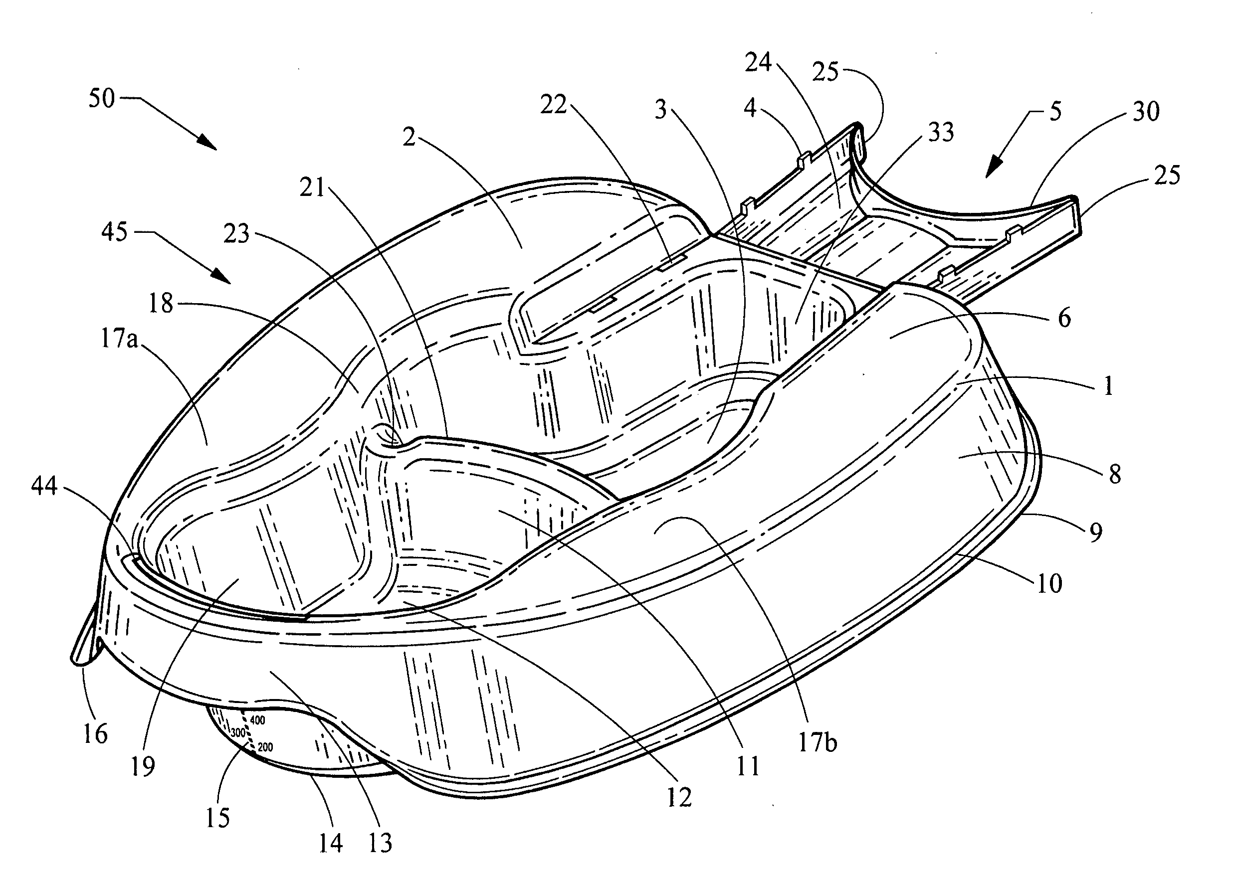
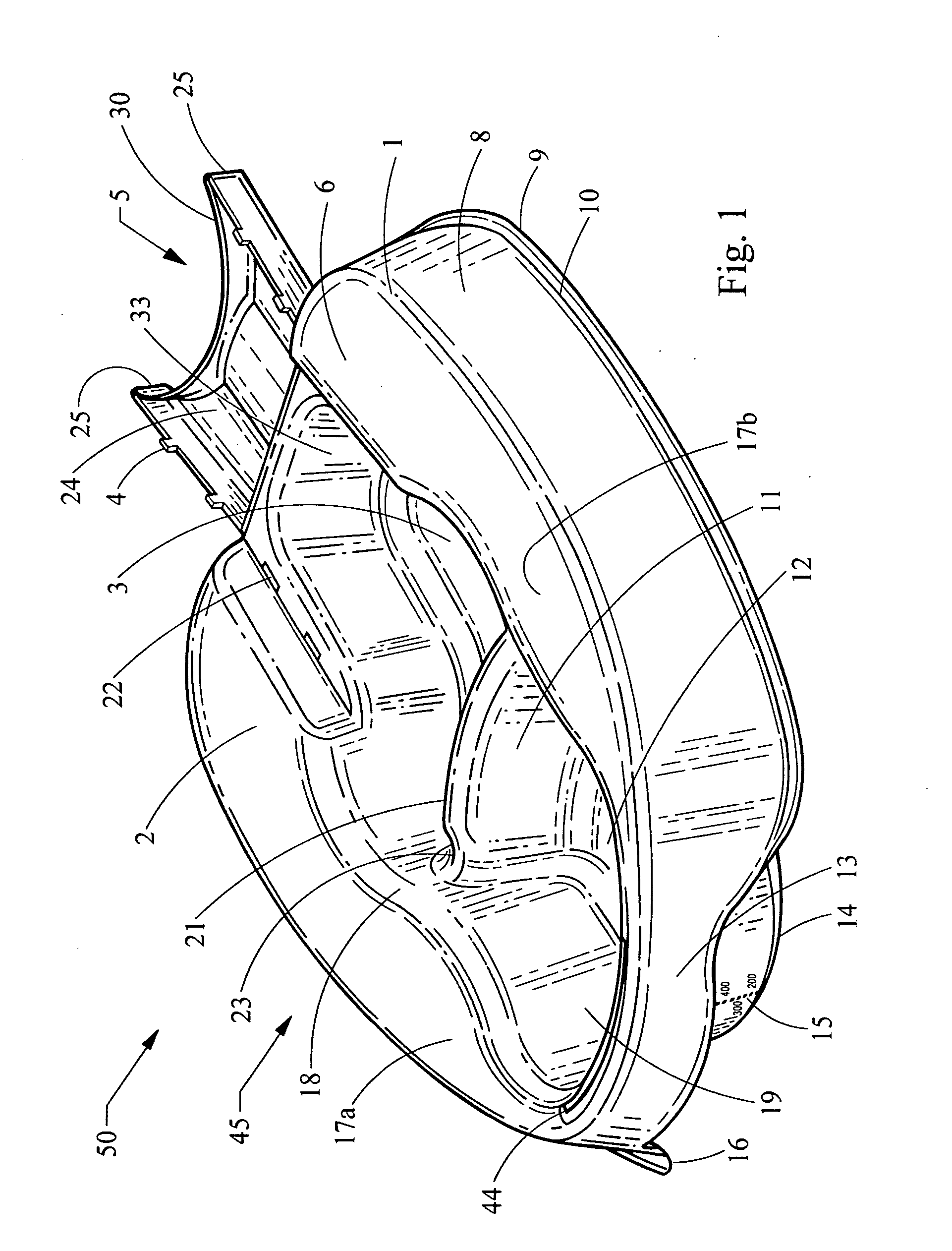
[0030] Referring to FIG. 1, a bedpan 50 includes a main body 45 and a living hinge 5. The main body 45 includes a top-left side 2 and a top-right side 6 (also referred to as “top sides 2, 6”) that form a general u-shape and that are ergonomically designed in a slightly concave shape. For example, the top sides 2, 6 include rounded edges to increase comfort to a user of the bedpan 50. Further, the two top sides 2, 6 are wide enough to aid in pressure distribution and decrease the likelihood of bedsore formation. In general, the top sides 2, 6 provide a seating area for the user.

[0031] A primary wing or flange 8 is connected near its top edge to a corresponding one of the top sides 2, 6. The primary wing 8 is further connected near its bottom edge to a generally flat area 10, which in turn is connected to a secondary wing or flange 9. The primary wing 8 is shaped to allow stacking and nesting of the bedpan 50 within another bedpan 50. For example, for stacking and / or nesting purposes...


PUM


Abstract

A bedpan for collecting waste includes a seating area and a plurality of cavities. The seating area is located in a main body of the bedpan. The plurality of cavities is formed within the seating area and includes a first cavity for collecting liquid waste and a second cavity for collecting solid waste. The first cavity and the second cavity are separated by a divider.

Description

CROSS-REFERENCE TO RELATED APPLICATION [0001] This application claims the benefit of U.S. Provisional Application No. 60 / 681,184, filed May 14, 2005, which is hereby incorporated by reference in its entirety.FIELD OF THE INVENTION [0002] The present invention relates generally to bedpans and, more particularly, to a bedpan for receiving liquid and solid waste in separate compartments. BACKGROUND OF THE INVENTION [0003] Originally, bedpans were manufactured using metal materials. Metal bedpans, however, include numerous disadvantages in comparison to plastic bedpans. For example, metal bedpans are expensive to manufacture, are uncomfortable to use, and are difficult to clean. Metal bedpans are uncomfortable because they are cold and hard to the touch of a user. Eventually, the industry began manufacturing plastic bedpans using a relatively inexpensive plastic material, e.g., high-density polyethylene (“HDPE”) or polypropylene (“PP”). Some advantages of using plastic material are a lo...

Claims


Application Information

Patent Timeline
IPC IPC(8): A61G9/00
CPCA61G2203/76A61G9/003
Inventor MOSLER, THEODORE J.JARNAGIN, SCOTT P.KOROGI, TODD M.DIMEO, ANDREW J. SR.
Owner MEDLINE IND LP
Why Eureka
Try Eureka