Composite material cutting equipment

A technology of cutting equipment and composite materials, applied in metal processing and other directions, can solve the problems of single structure and low cutting applicability

Inactive Publication Date: 2021-08-20
HEBEI NORTH UNIV
View PDF0 Cites 0 Cited by
  • Summary
  • Abstract
  • Description
  • Claims
  • Application Information

AI Technical Summary

Problems solved by technology

[0005] The purpose of the embodiments of the present invention is to provide composite material cutting equipment, aiming to solve the problem o...

Method used


Image

  • Composite material cutting equipment
  • Composite material cutting equipment
  • Composite material cutting equipment

Examples


Embodiment Construction

[0039] In order to make the object, technical solution and advantages of the present invention clearer, the present invention will be further described in detail below in conjunction with the accompanying drawings and embodiments. It should be understood that the specific embodiments described here are only used to explain the present invention, not to limit the present invention.

[0040] The specific implementation of the present invention will be described in detail below in conjunction with specific embodiments.

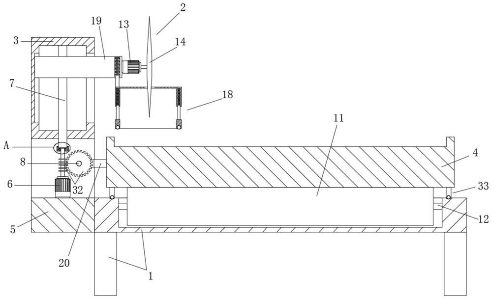
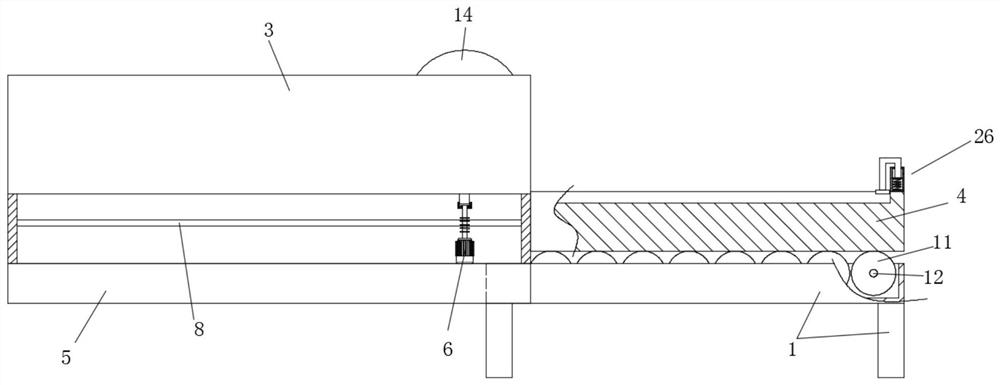
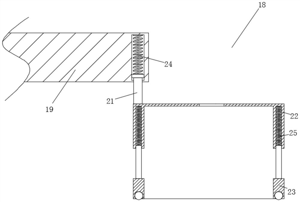
[0041] to combine Figure 1-7 As shown, the structural diagram of the composite material cutting equipment provided for an embodiment of the present invention includes:

[0042] Install base 1, cutting assembly 2, mounting bracket 3 for installing cutting assembly 2 and placing platform 4;

[0043] The placement platform 4 is slidably arranged on the installation base 1;

[0044] The cutting assembly 2 is slidably arranged on the mounting bracket 3;

[0045] ...


PUM


Abstract

The invention is suitable for the related field of machinery, and provides composite material cutting equipment which comprises a mounting base, a cutting assembly, a mounting bracket for mounting the cutting assembly and a placing platform. The composite material cutting equipment further comprises a positioning seat, a driving motor, a first reciprocating screw rod and a second reciprocating screw rod. The positioning seat is arranged on the side surface of the end part of the mounting base. The driving motor is used for driving the cutting assembly to longitudinally move and the placing platform to horizontally move. The first reciprocating screw rod is rotationally arranged on the mounting bracket, is coaxial with an output shaft of the motor, is in transmission connection with the output shaft of the motor through a ratchet wheel and pawl pair, and is used for driving the cutting assembly to vertically reciprocate. The second reciprocating screw rod is rotationally arranged on the mounting bracket, is spatially perpendicular to the output shaft of the motor, is in transmission connection with the output shaft of the motor through a worm and gear pair, and is used for driving the placing platform to horizontally reciprocate towards the cutting assembly. The problems that existing cutting equipment is single in structure, a single power source can only control a single acting mechanism, and the overall cutting applicability is low are solved.

Description

technical field [0001] The invention belongs to the related field of machinery, and in particular relates to a composite material cutting device. Background technique [0002] Composite materials are materials with new properties composed of two or more materials with different properties through physical or chemical methods on the macroscopic (microscopic) level. Various materials learn from each other in terms of performance and produce synergistic effects, so that the comprehensive performance of the composite material is better than that of the original constituent materials to meet various requirements. The matrix materials of composite materials are divided into two categories: metal and non-metal. Commonly used metal substrates are aluminum, magnesium, copper, titanium and their alloys. Non-metallic substrates mainly include synthetic resin, rubber, ceramics, graphite, carbon, etc. Reinforcement materials mainly include glass fiber, carbon fiber, boron fiber, arami...

Claims


Application Information

Patent Timeline
IPC IPC(8): B26D1/16B26D5/06B26D7/20B26D7/06B26D7/22
CPCB26D1/16B26D5/06B26D7/0616B26D7/20B26D7/22
Inventor 田野王校苗杨振兴党玲岩褚克
Owner HEBEI NORTH UNIV
Why Eureka
Try Eureka