Anchoring Element

a technology of anchoring elements and screws, applied in the direction of fastening means, screws, dowels, etc., can solve the problems of high cost, high cost, and the inability to clean the borehole, and achieve the effect of accelerating the setting of the fastening assembly and increasing the reliability

Inactive Publication Date: 2010-01-28
HILTI AG
View PDF12 Cites 0 Cited by
  • Summary
  • Abstract
  • Description
  • Claims
  • Application Information

AI Technical Summary

Benefits of technology

[0051]During driving of the fastening element or the fastening assembly in a borehole, simultaneously, cleaning of the borehole is carried out as a result of brushing of the anchoring element along the borehole wall. As a result, drillings, which are produced during drilling of the borehole, are accumulated at the borehole bottom and, if required, are accumulated in the hardenable mass, and are not released anymore in a large amount into environment. A separate cleaning of the borehole before setting of the fastening assembly or the fastening element is not any more necessary, despite of which high end loads with the anchored fastening assembly are achieved. Further, the anchoring assemblies provide for protection against splash of the hardenable mass during driving of the fastening assembly in the borehole.
[0052]With the elimination of the cleaning step, the reliability is increased, and the setting of the fastening assembly is accelerated. No additional devices are necessary, and the surrounding air is not contaminated by drillings. Further the fastening assemblies with the inventive anchoring element insure, a sufficient covering of the shaft of the fastening element along its entire anchoring length with a hardenable mass in the borehole.

Problems solved by technology

Cleaning of the borehole involves additional expenses and requires separate auxiliary means necessary to achieve advantageous results and which are not always available to the user.
The drawback of the fastening element disclosed in DE 24 23 433 A1 consists in that the fastening element can be loaded only after the hardenable mass has hardened.
The drawback of the fastening element described above consists in that in view of the shaped outer profile of the shaft of the fastening element, the flat ring-shaped anchoring elements easily incline in a plane extending transverse to the longitudinal axis of the shaft and, as a result, the shaft section that projects from the borehole after setting of the fastening element, does not extend perpendicular to the surface of the constructional component.
Further, for cleaning of the borehole wall sufficient for a chemical anchoring and for an adequate anchoring of the fastening element, a sufficient number of anchoring elements should be provided and which are separately mounted on the shaft of the fastening element, which is expensive.

Method used


Image

  • Anchoring Element
  • Anchoring Element
  • Anchoring Element

Examples


Embodiment Construction

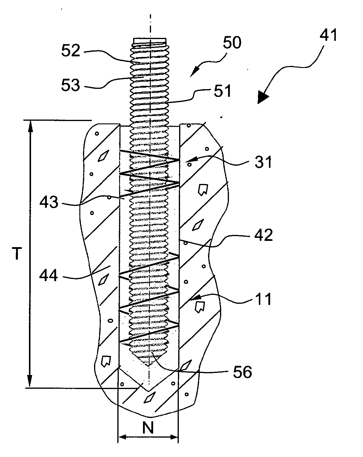
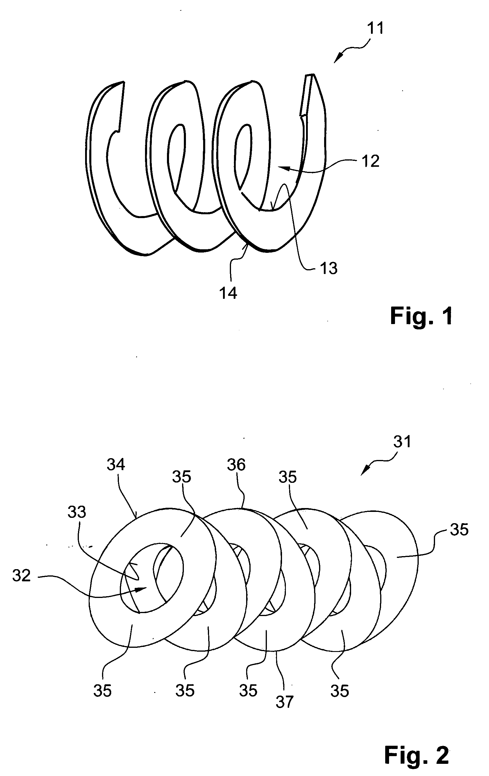
[0066]A helices-shaped anchoring element 11 according to the present invention, which is shown in FIG. 1, is formed of a strip and has a through-opening 12 for a shaft of a fastening element. The helix-shaped anchoring element 11 extends over an angular region of more than 360°. In the embodiment shown in FIG. 1, the anchoring element 11 extends thrice around the opening 12, which corresponds to an angular region of 1080°. The multiple of 360° that defines the extent of the strip-shaped anchoring element 11 need not be a whole number. E.g., if the strip extends over an angular region of 480°, it would extend 1.3 times around the through-opening 12. The anchoring element 11 can be easily adapted to site condition or different loads, e.g., by being cut to a length.

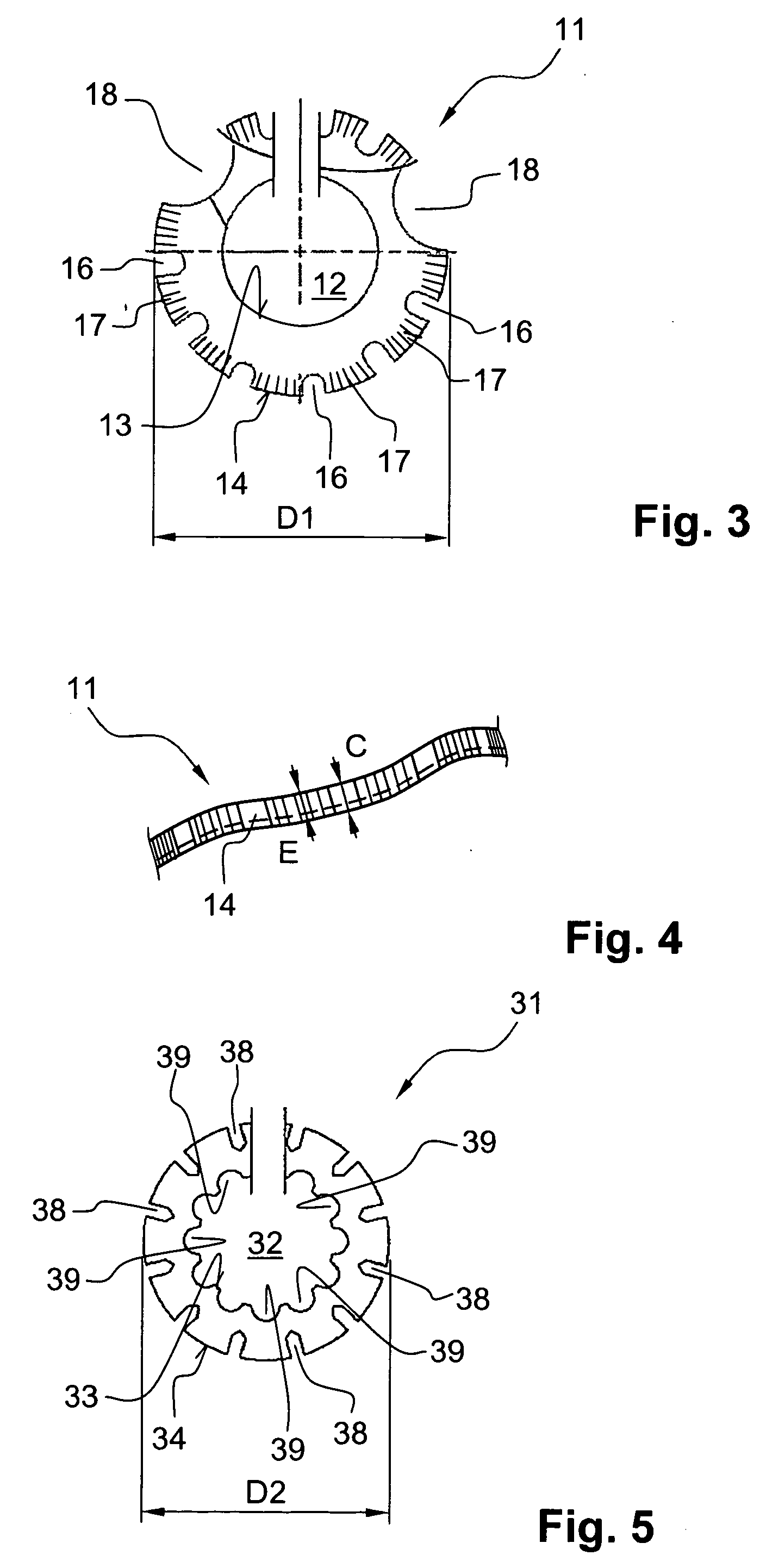
[0067]The anchoring element 11 has an inner edge 13 adjacent to the through-opening 12, and an outer edge 14 remote from the through-opening 12. The anchoring element 11 is formed of metal, preferably, sheet steel, by a stam...


PUM


Abstract

An anchoring element for being mounted on a shaft (52; 62; 72; 92) of a fastening element (51; 61; 71; 91) has a through-opening for the shaft (52; 62; 72; 92) and a strip extending around the through-opening (12; 32; 82) over an angular region of more than 360°.

Description

BACKGROUND OF THE INVENTION[0001]1. Field of the Invention[0002]The present invention relates to an anchoring element having a through-opening for being mounted on a shaft of a fastening element which has an outer profile. The present invention also relates to a fastening assembly anchorable in a borehole of a constructional component with a hardenable mass and having a fastening element and at least one anchoring element, and to a fastening arrangement with such a fastening assembly.[0003]2. Description of the Prior Art[0004]It is known to chemically anchor a fastening element in a borehole with a hardenable mass that is brought into the borehole before or after insertion of the fastening element in the borehole. The fastening element can be formed, e.g., as a threaded rod provided along its entire longitudinal extent with a thread that forms the outer profile. When such a fastening element is chemically anchored, a rupture can occur along a contact region between the shaft and the...

Claims


Application Information

Patent Timeline
Patent Type & Authority Applications(United States)
IPC IPC(8): F16B13/06F16B13/04
CPCF16B37/12F16B39/20F16B39/021
Inventor BIANCHI, PIETROTOGNINI, ROGERSANDER, BERNHARDLUTZ, CLEMENSAPPL, JOERGKONRAD, WALTER
Owner HILTI AG
Why Eureka
Try Eureka