AI technical title is built by Patsnap AI team. It summarizes the technical point description of the patent document.
a technology for cleaning devices and submerged surfaces, which is applied in the direction of gymnasiums, buildings, construction, etc., can solve the problems of jerking of the hose, displacement of the pool cleaner apparatus over the surface to be cleaned, and emitted a hammering sound which can be irritating to users, so as to improve the maneuverability of the cleaner
Inactive Publication Date: 2006-11-16
PHILLIPSON BRIAN H +2
View PDF2 Cites 5 Cited by
Summary
Abstract
Description
Claims
Application Information
AI Technical Summary
This helps you quickly interpret patents by identifying the three key elements:
Problems solved by technology
Method used
Benefits of technology
Benefits of technology
[0014] In view of the foregoing background, it is therefore an object of the present invention to provide a device for cleaning submerged surfaces such as those found in swimming pools. In particular, it is intended that the device is minimally intrusive with regard to both noise and overall size, is functionally and mechanically simple, is easy to install, is less prone to entrap debris than existing devices, incorporates easy access to the suction chamber for the removal of entrapped debris and includes means for maneuvering away from obstacles. Yet another object of the invention is to provide steering for directing the cleaning device on the submerged surface to maneuver away from obstacles. Further objects and advantages of the invention will become more apparent from a reading of the following description of the invention and embodiments thereof. It is also contemplated that the system and method are useful in fluid environments other than swimming pools and spas.
[0018] When the suction pump is activated, it causes a flow of fluid through the chamber and primarily through a first passage between the front face of the flap member and the front wall of the chamber. The flow through this passage will cause the flap member to be drawn to a position in close proximity or contact with the front wall of the chamber. This action will substantially close the first passage, substantially interrupt the flow of fluid through the first passage, and cause a quantity of water to impact a front face of the flexible portion of the flap member. Restricted flow of fluid will occur between a side of the flexible portion and a wall of the chamber and then via a. second passageway between a rear face of the flap member and a rear wall of the chamber. In this manner, the flexible portion acts as a baffle to water flow through the second passageway. Simultaneous with the interruption of fluid flow, the action of the pump will cause a lower fluid pressure zone in the suction hose and in the volume of the chamber downstream of a flexible portion of the flap member. The impact of fluid on the front face of a flexible portion and the lower pressure impinging upon the rear face of a flexible portion of the flap member each cause the flexible portion to deflect towards the lower pressure zone. This action upon and of the flexible portion will apply leverage to the rigid portion and cause the rigid portion and remainder of the flap member to pivot away from the front wall of the chamber, thereby reopening the passage for fluid to be drawn through the chamber. This sequence of events is repeated for as long as the pump is in operation, and causes an automatic reciprocating movement of the rigid portion of the flap member and a regular interruption in fluid flow through the suction chamber for providing a forward movement of the pool cleaner along the surface to be cleaned.
[0019] In a preferred embodiment, the flexible portion comprises two lengths of resilient rubber-like material separately mounted closer to the chamber entrance end and attached to or in close proximity to the rear wall of the suction chamber. This arrangement provides a volume between the two flexible portions and the walls of the chamber. The sides of the flexible portions are in close proximity with at least two walls of the chamber thereby enabling the flexible portions to perform as baffles and restrict the flow of water from said volume and the flow passage through the chamber. At least one aperture in a section of the wall of the chamber may be provided to allow, when the cleaner is submerged in a liquid, communication between water contained in said volume and water outside of the chamber. During operation of the device, this arrangement provides a buffer zone of relatively higher pressure impinging on one face of each length of flexible portion, the other face of each such flexible portion being in contact with water at a lower pressure as it is drawn through the chamber towards the hose and suction pump. This arrangement significantly diminishes the propensity of water-borne debris to become lodged between a side of a flexible portion of the flap member and a wall of the chamber which would impair operation of the flap valve.
[0020] Sealing means is attached to the rigid portion of the flap member to minimize the flow of water between the sides of a rigid portion and the walls of the suction chamber. The head of the cleaner is connected to surface engaging means such as a detachable shoe suitable for engaging the surface to be cleaned and for supporting the head. To improve the ability of the cleaner to orient the surface engaging means against the surface to be cleaned, floats and weights are attached to parts of the cleaner. To improve the suction grip of the cleaner to the surface to be cleaned, a flexible sealing flange is detachably connected to the shoe. In a preferred embodiment, at least one aperture is provided in the sealing flange such that water and debris may be drawn through the aperture from the upper surface of the sealing flange and then into the entrance end of the suction chamber proximate the surface to be cleaned.
[0022] To assist the steering, improve maneuverability of the cleaner and help avoid the establishment of repetitive courses across the surface to be cleaned, the sealing flange includes at least one out of round side and / or finger and / or stiffening means suitable for engaging a swimming pool wall or obstacle while the surface engaging means are engaged with the floor of the swimming pool.
Problems solved by technology
When in use for cleaning a swimming pool, the hose becomes filled with water and the continuous opening and closing of the valve causes the hose to jerk.
A pulsating flow of fluid through the assembly results and in forces cause the displacement of the pool cleaner apparatus over a surface to be cleaned.
Typically, a flapper valve used in such devices emit a hammering sound which can be irritating to a user.
Many devices known in the art are large and cumbersome.
This impairs its maneuverability and effectiveness in smaller-sized pools and those where the transitions between the walls and / or between the floor and walls are sharp or tight.
Debris such as twigs, berries and stones may become trapped in the operating head between the flapper valve and the valve seats.
In order to clear debris or perform other maintenance tasks, it is difficult to gain access to the valve chamber, the flapper valve, valve seats and the openings in communication with the passages.
Sticks and larger pieces of debris may damage or puncture the flexible tubular member or may become entrapped in the members.
Access to and removal of the flexible tubular member which is enclosed within a chamber is difficult and typically a non-technical person will avoid attempting easy repair.
Often times, the pool cleaner provides a strong suction for effectively moving over the surface to be cleaned, but to its detriment fails to create a suction flow through the cleaner sufficient to remove sand located on the surface to be cleaned.
Method used
Image
Click on the blue label to locate the original text in one second.
Reading with bidirectional positioning of images and text.
Examples
Embodiment Construction
[0065] The present invention will now be described more fully hereinafter with reference to the accompanying drawings, in which preferred embodiments of the invention are shown. This invention may, however, be embodied in many different forms and should not be construed as limited to the embodiments set forth herein. Rather, these embodiments are provided so that this disclosure will be thorough and complete, and will fully convey the scope of the invention to those skilled in the art. Like numbers refer to like elements throughout.
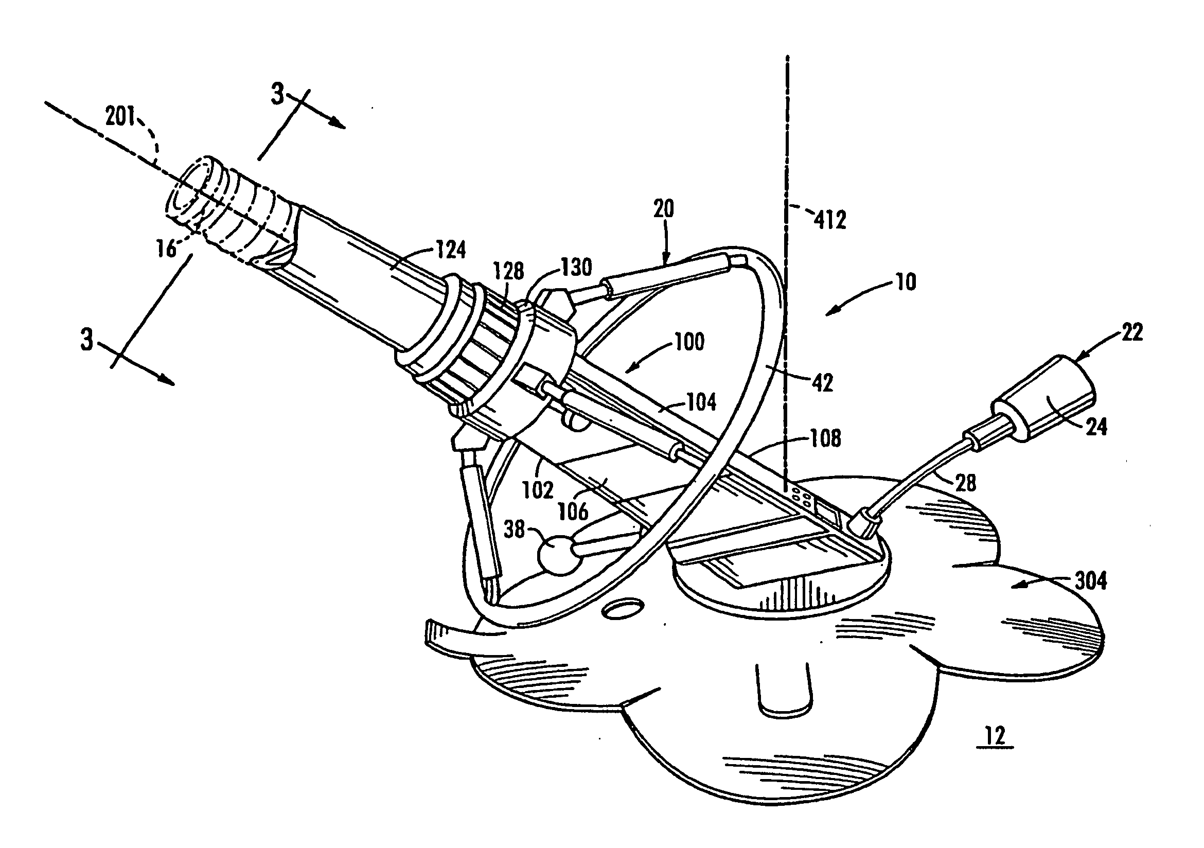
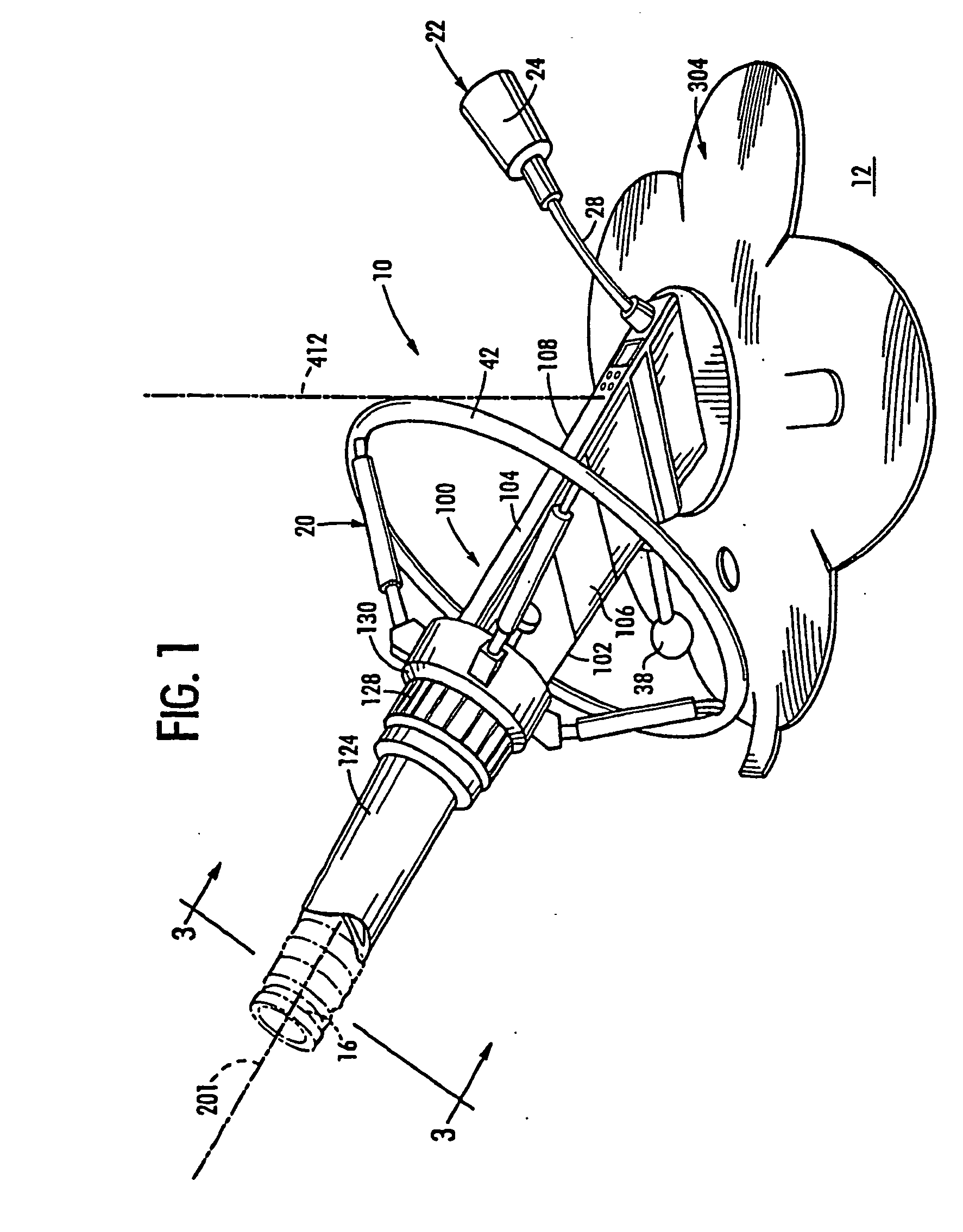
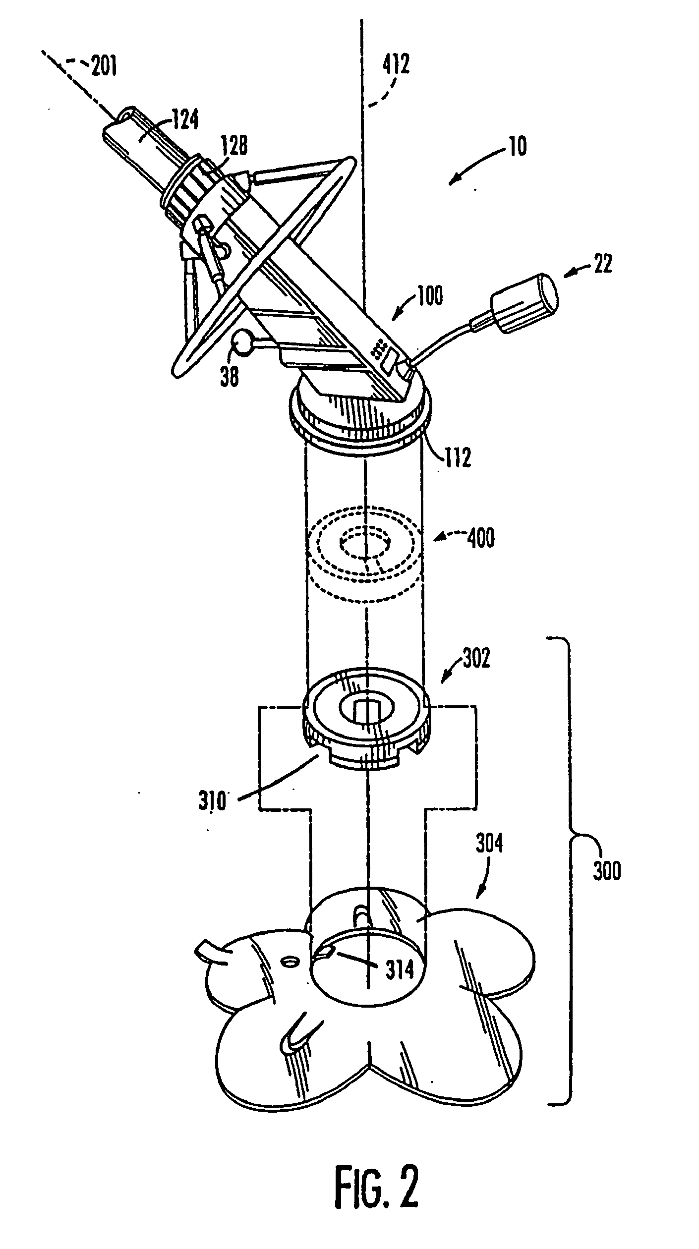
[0066] As initially described with reference to FIGS. 1-4, a swimming pool cleaning device, the pool cleaner 10, for automatically cleaning a surface 12 submerged in liquid 14 comprises a forwardly inclined housing 100 having rigid walls 102, 104, 106, and 108 forming a flow passage or chamber 110 extending therethrough from an inlet or entrance end 112 which in use is proximate the surface 12 to be cleaned, to an outlet or exit end 114 for connection to...
PUM
Abstract
A swimming pool cleaning device for automatically cleaning a submerged surface includes a forwardly inclined housing forming a flow passage including a flow control valve. A flexible planar disc extends around an inlet to the flow passage for engaging the surface to be cleaned. The flexible planar member includes slits extending from the peripheral edge inward toward the central opening to form a pedal-like segmented flange for splaying of each segment in response to travel of the cleaner over an irregularly contoured surface and facilitate an effective frictional contact with the surface. A steering mechanism driven by fluid flow through the housing causes the housing to rotate about the planar disc.
Description
CROSS-REFERENCE TO RELATED APPLICATIONS [0001] This application is a continuation of U.S. application Ser. No. 10 / 000,807, filed Nov. 2, 2001, which is a continuation of application Ser. No. 09 / 490,956, filed Jan. 24, 2000, now U.S. Pat. No. 6,311,353, for “Submerged Surface Pool Cleaning Device,” which is a continuation of application Ser. No. 09 / 113,832, filed Jul. 10, 1998, now U.S. Pat. No. 6,119,293, for “Submerged Surface Pool Cleaning Device,” which was related to Provisional Applications having Ser. No. 60 / 052,296, filed on Jul. 11, 1997 for “Steering Apparatus and Method for Pool Cleaner” and Ser. No. 60 / 052,625, filed Jul. 15,1997 for “Submerged Surface Cleaning Device,” all of which are commonly owned with the instant application and all of which are incorporated herein by reference.FIELD OF THE INVENTION [0002] This invention relates generally to self-propelled devices for cleaning submerged surfaces. More particularly, it relates to a swimming pool cleaning device incor...
Claims
Application Information
Patent Timeline
Application Date:The date an application was filed.
Publication Date:The date a patent or application was officially published.
First Publication Date:The earliest publication date of a patent with the same application number.
Issue Date:Publication date of the patent grant document.
PCT Entry Date:The Entry date of PCT National Phase.
Estimated Expiry Date:The statutory expiry date of a patent right according to the Patent Law, and it is the longest term of protection that the patent right can achieve without the termination of the patent right due to other reasons(Term extension factor has been taken into account ).
Invalid Date:Actual expiry date is based on effective date or publication date of legal transaction data of invalid patent.
Patent Type & AuthorityApplications(United States)
IPC IPC(8): E04H4/16
CPCE04H4/1663
InventorPHILLIPSON, BRIAN H.SEBOR, PAULSEBOR, DANIELA

