Fluid machine

a technology of heat cycle and electric motor, which is applied in the direction of machines/engines, liquid fuel engines, light and heating apparatus, etc., can solve the problems of increasing electric power consumption, unnecessary load being applied to the electric motor, and not reaching a sufficient high pressure of refrigerant, etc., and achieves the effect of increasing the amount of collected energy and avoiding unnecessary consumption of driving for

Inactive Publication Date: 2006-11-16
DENSO CORP +1
View PDF8 Cites 48 Cited by
  • Summary
  • Abstract
  • Description
  • Claims
  • Application Information

AI Technical Summary

Benefits of technology

[0023] The present invention is made in view of the foregoing problems, and has an object to provide a fluid machine for collecting waste heat from an automotive engine by Rankine cycle to generate electric power. In the fluid machine, a useless consumption of driving force (electric power...

Problems solved by technology

In this case, the expansion device starts with rotation in a condition that the refrigerant has not yet reached a sufficient high pressure.
A useless load would be thereby applied to the electric motor, and it is a disadvantage that electric power consumption would be increased.
However, during an intermediate period in which the pressure has not reached a predetermined pressure, a position of the movable scroll is not stable because of the operation of the crank mechanism, and thereby the movable scroll wrap may be repeatedly brought into con...

Method used


Image

  • Fluid machine
  • Fluid machine
  • Fluid machine

Examples


first embodiment

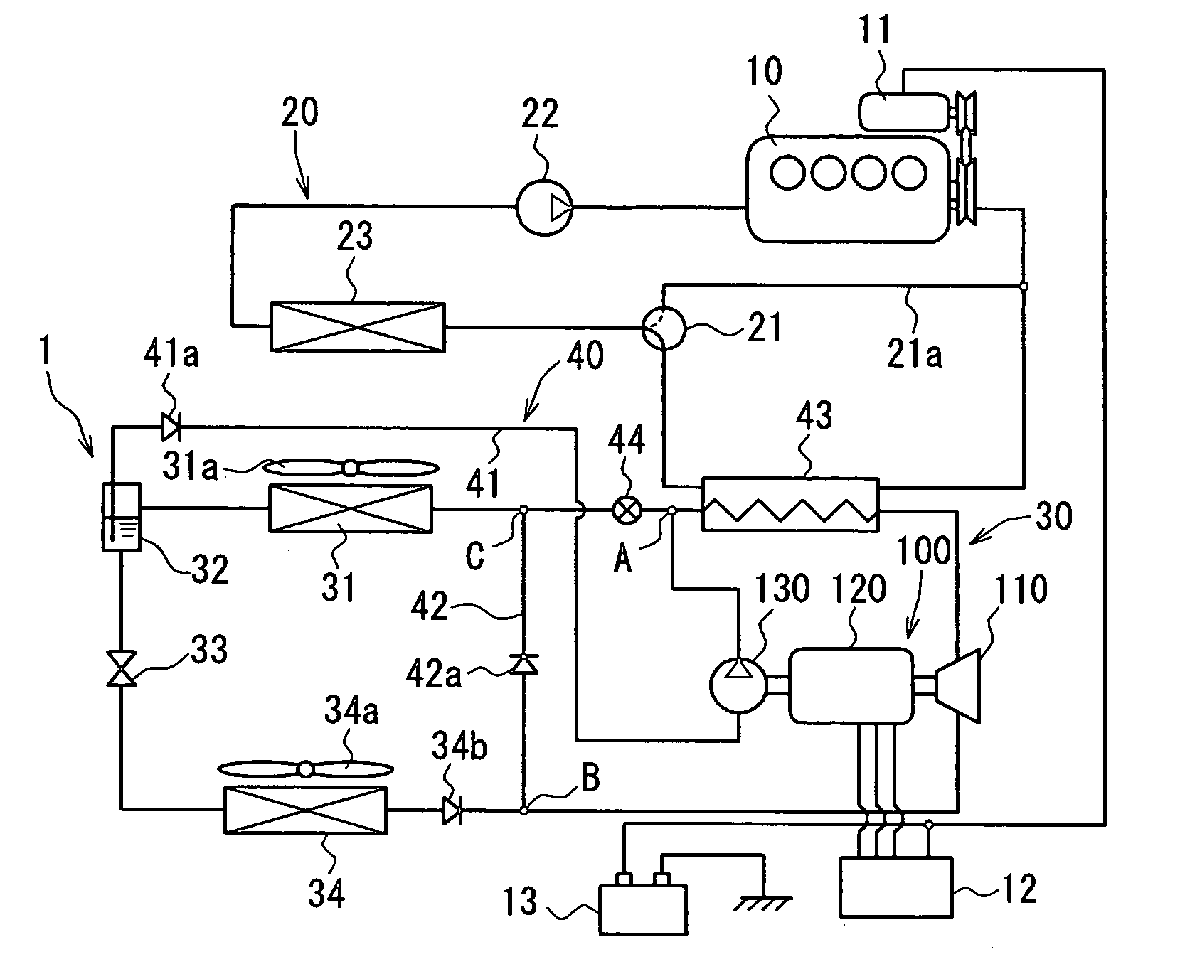
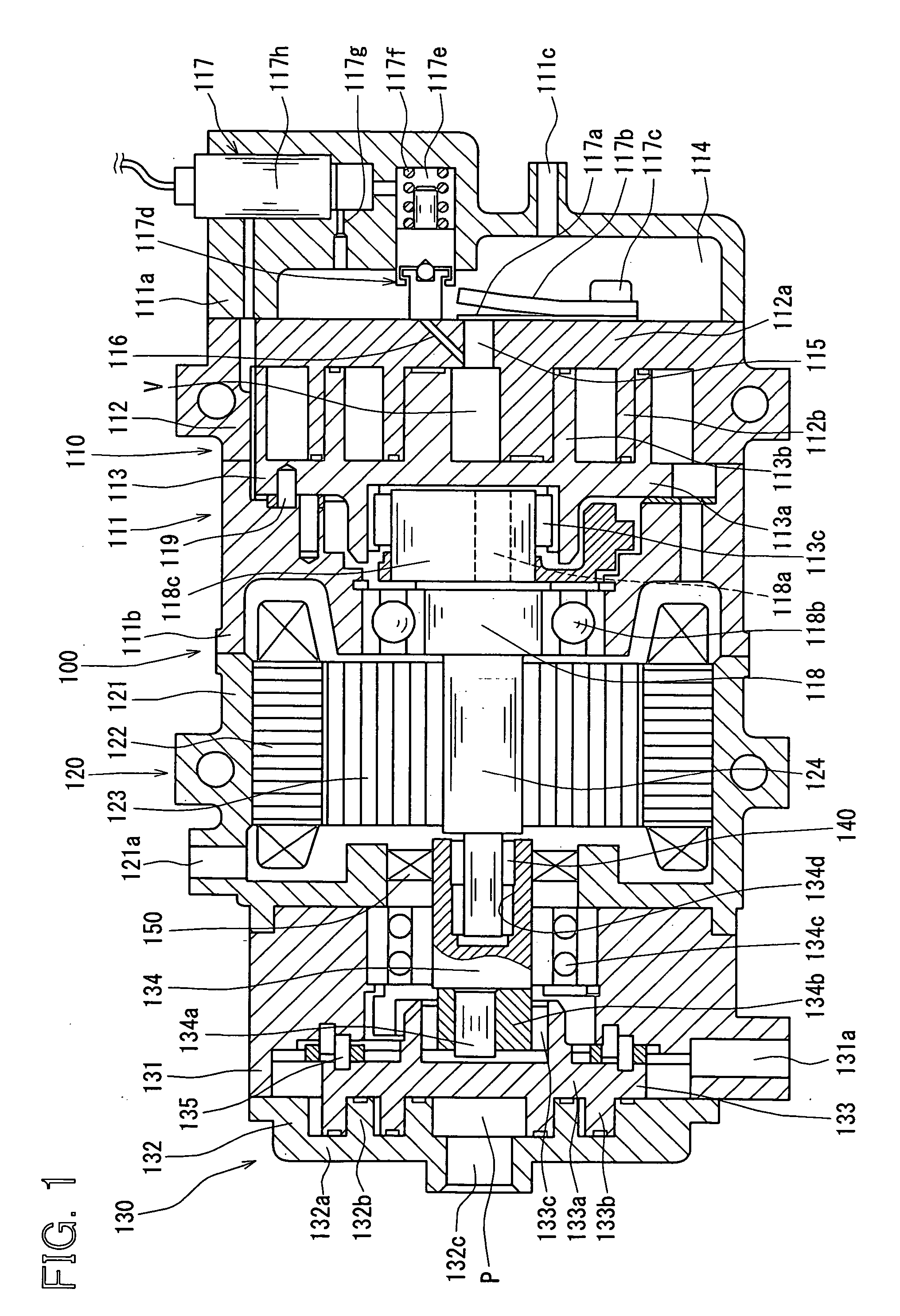
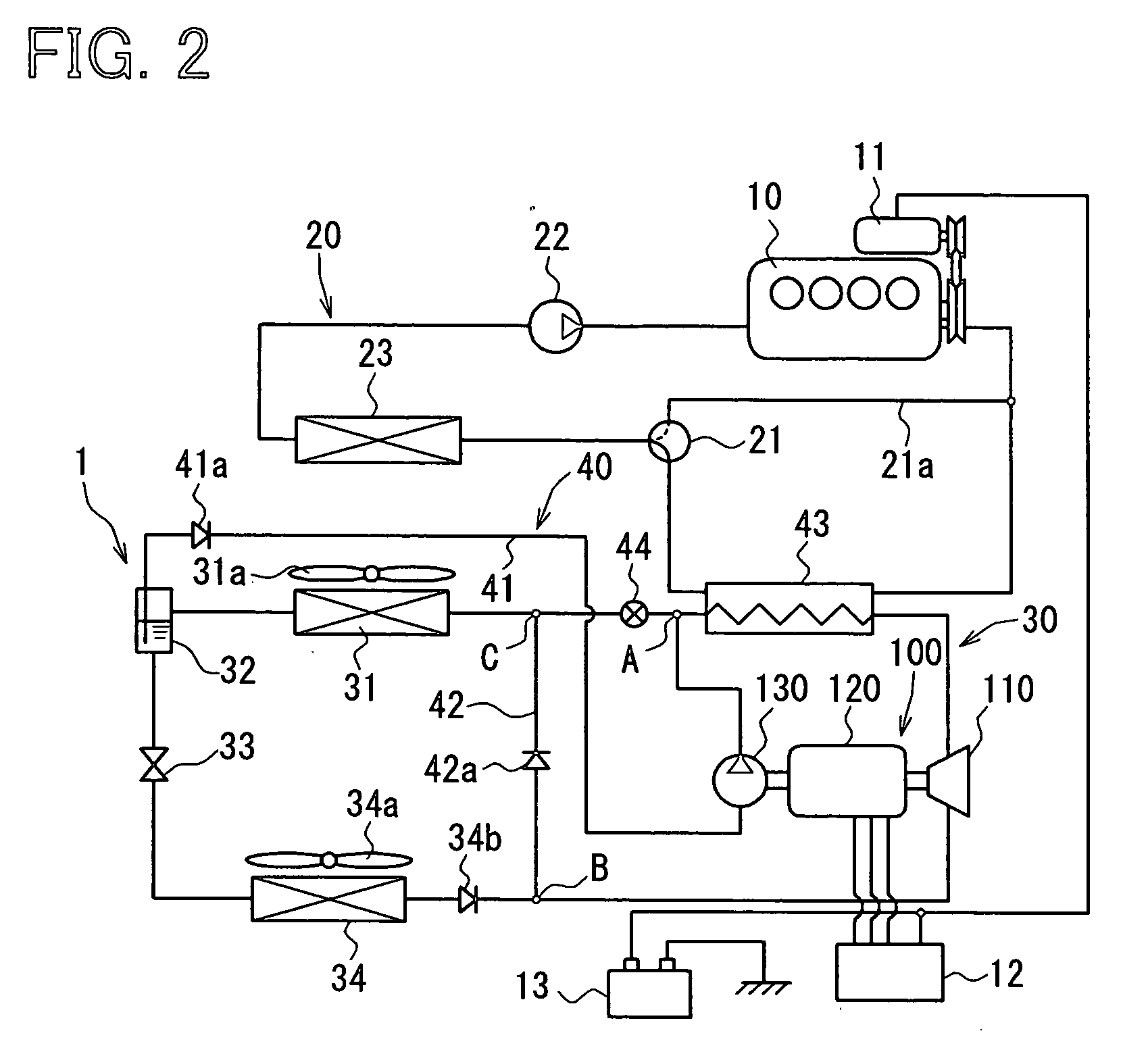
[0053] Embodiments of the present invention will be explained with reference to the drawings. FIG. 1 is a cross sectional view showing a complex fluid machine 100 (in which a compressor device, an expansion device and a refrigerant pump are integrally formed into one unit), whereas FIG. 2 is a schematic diagram showing a refrigerating apparatus to which the fluid machine 100 of the present invention is applied. According to the embodiments of the present invention, the fluid machine 100 is applied to a refrigerating apparatus 1 for an automotive vehicle, which has a refrigerating cycle 30 and Rankine cycle 40.

[0054] At first, a structure of the complex fluid machine 100 will be explained with reference to FIG. 1. The complex fluid machine 100 comprises an expansion-compressor device 110 having both functions of a compressor device and an expansion device, a motor generator 120 having both functions of an electric power generator and an electric motor, and a refrigerant pump 130.

[0...

second embodiment

[0116]FIGS. 5A and 5B show a second embodiment for the crank mechanism 118 of the swing-ring type, wherein FIG. 5A is an oblique view, and FIG. 5B is a cross sectional view showing the driving pin 1181a and the bushing 1182. FIGS. 6A to 6C show the second embodiment for the crank mechanism 118 of the slider type, wherein FIG. 6A is an oblique view, FIG. 6B is a cross sectional view showing the driving pin 1181a and the bushing 1182, and FIG. 6C is a cross sectional view taken along a line VIC-VIC of FIG. 6B.

[0117] The second embodiment shown in FIGS. 5A-5B and FIGS. 6A-6C is different from the crank mechanism 118 shown in FIGS. 3A-3B and FIGS. 4A-4C, in that a spring 162 is provided in the bushing 1182, as the biasing means 160, in order to bias the movable scroll 113 in the direction that the movable scroll wraps 113b is separated from the contact with the fixed scroll wrap 112b. In FIG. 5B, a numeral 163 designates a spring stopper, and a numeral 164 designates a sliding member f...

third embodiment

[0120]FIGS. 7A and 7B show a bypass mechanism 170 according to a third embodiment of the present invention. FIG. 7A is an explanatory drawing showing relative positions of the movable and fixed scrolls and bypass holes 171. FIG. 7B is an enlarged cross sectional view taken along a line VIIB-VIIB in FIG. 7A. A clearance is formed between the movable and fixed scroll wraps 112b and 113b, so that both scroll wraps 112b and 113b may not be brought into contact with each other at more than two points in an angular range of larger than 360°. The bypass holes 171 are provided in the base plate 112a of the fixed scroll 112 for operatively communicating the bypass holes 171 with the discharge port 115.

[0121] More specifically, the bypass holes 171 are opened to the working chamber(s) V reaching its minimum volume as shown in FIG. 7A, and the bypass holes 171 are communicated with the discharge port 115 by a bypass passage 171a through check valves 172. As shown in FIG. 7B, each of the check...


PUM


Abstract

A fluid machine has a scroll type expansion device which is operated by a high temperature high pressure refrigerant. The refrigerant is heated by use of waste heat from an engine for a vehicle. The fluid machine further has a motor generator for generating electric power when it is driven by a rotational force produced at the expansion device, wherein a rotating shaft of the motor generator is coupled to a movable scroll of the expansion device via a crank mechanism. A biasing member is provided for biasing the crank mechanism in a direction that the movable scroll wrap is separated from a contact in a circumferential direction with a fixed scroll wrap. Pressure of the refrigerant in a working chamber in the center portion is thereby equalized to the pressure in the outer peripheral portion, at a startup period of the expansion mode.

Description

CROSS REFERENCE TO RELATED APPLICATION [0001] This application is based on Japanese Patent Application Nos. 2005-139111 filed on May 11, 2005, 2005-164037 filed on Jun. 3, 2005 and 2006-44420 filed on Feb. 21, 2006, the disclosures of which are incorporated herein by reference. FIELD OF THE INVENTION [0002] The present invention relates to a heat cycle apparatus having a function of Rankine cycle. [0003] The present invention further relates to a fluid machine including a scroll type expansion-compressor device having both functions of an expansion device and a compressor device, a motor generator also having both functions of an electric motor and an electric power generator. The fluid machine has a compression mode for compressing working fluid by driving the expansion-compressor device with the motor generator, and an electric power generating mode for generating electric power by driving the motor generator with the expansion-compressor device. BACKGROUND OF THE INVENTION [0004]...

Claims


Application Information

Patent Timeline
IPC IPC(8): F25B23/00F01C1/00F25B1/00F03C2/00
CPCF01C11/004F01C13/00F01K23/02F01K25/08F04C18/0215F25B2400/14F04C29/0057F04C2240/45F25B1/04F25B27/02F04C29/0035Y02A30/274
Inventor TAKEUCHI, YASUHIROUNO, KEIICHIHISANAGA, SHIGERUASA, HIRONORIYAMANAKA, TAKASHIINABA, ATSUSHIUCHIDA, KAZUHIDEOGAWA, HIROSHIKAWAMOTO, YOICHIROKISHITA, HIROSHI
Owner DENSO CORP
Why Eureka
Try Eureka