Shielded electrical transmission cables and methods for forming the same

a technology of shielded electrical transmission cables and shielded conductors, which is applied in the direction of power cables, cables, insulated conductors, etc., can solve the problems of significantly heavier copper and more expensive than aluminum

Inactive Publication Date: 2006-11-16
COMMSCOPE INC
View PDF21 Cites 31 Cited by
  • Summary
  • Abstract
  • Description
  • Claims
  • Application Information

AI Technical Summary

Problems solved by technology

However, copper is significantly heavier and more costly than aluminum.

Method used


Image

  • Shielded electrical transmission cables and methods for forming the same
  • Shielded electrical transmission cables and methods for forming the same
  • Shielded electrical transmission cables and methods for forming the same

Examples


Embodiment Construction

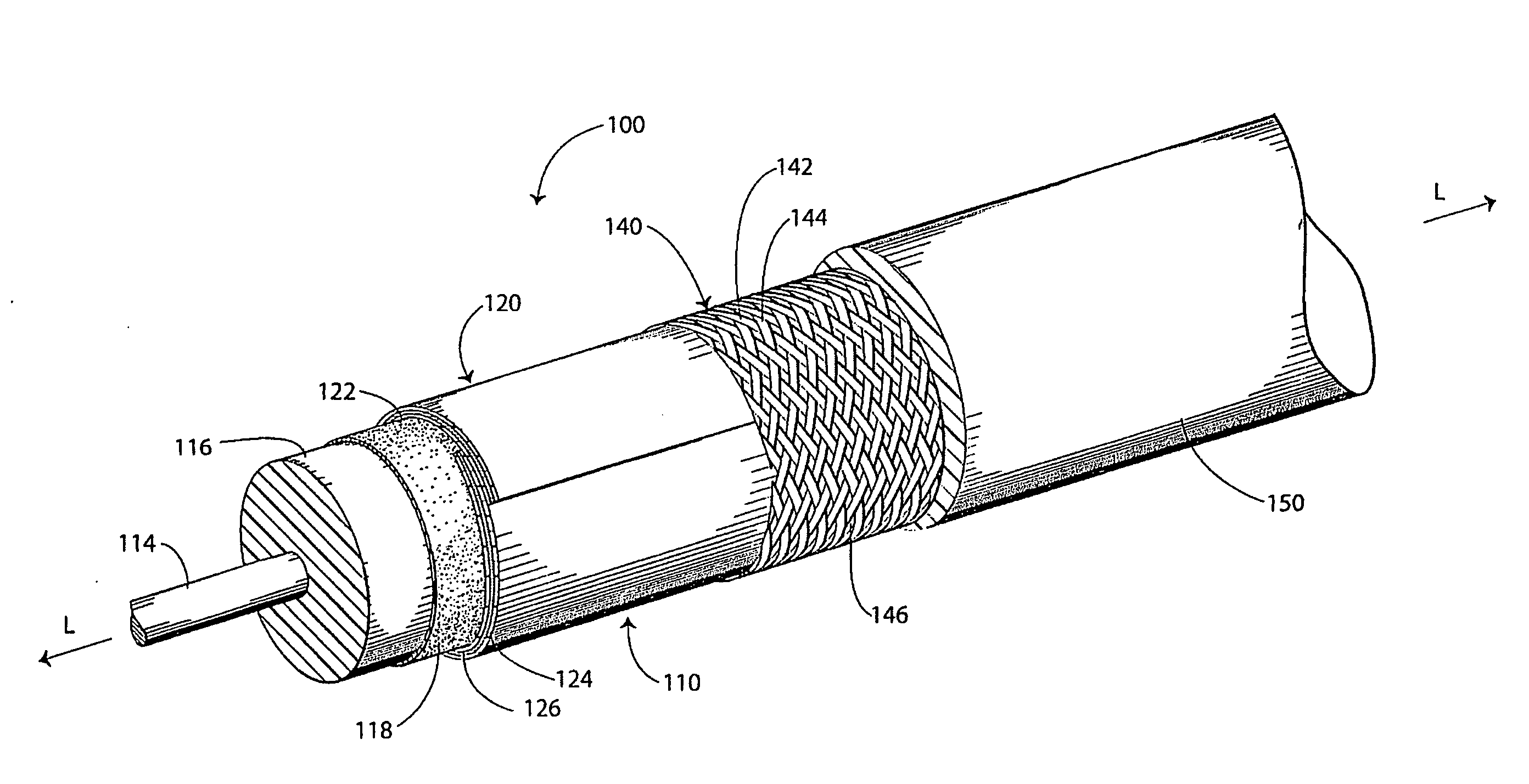
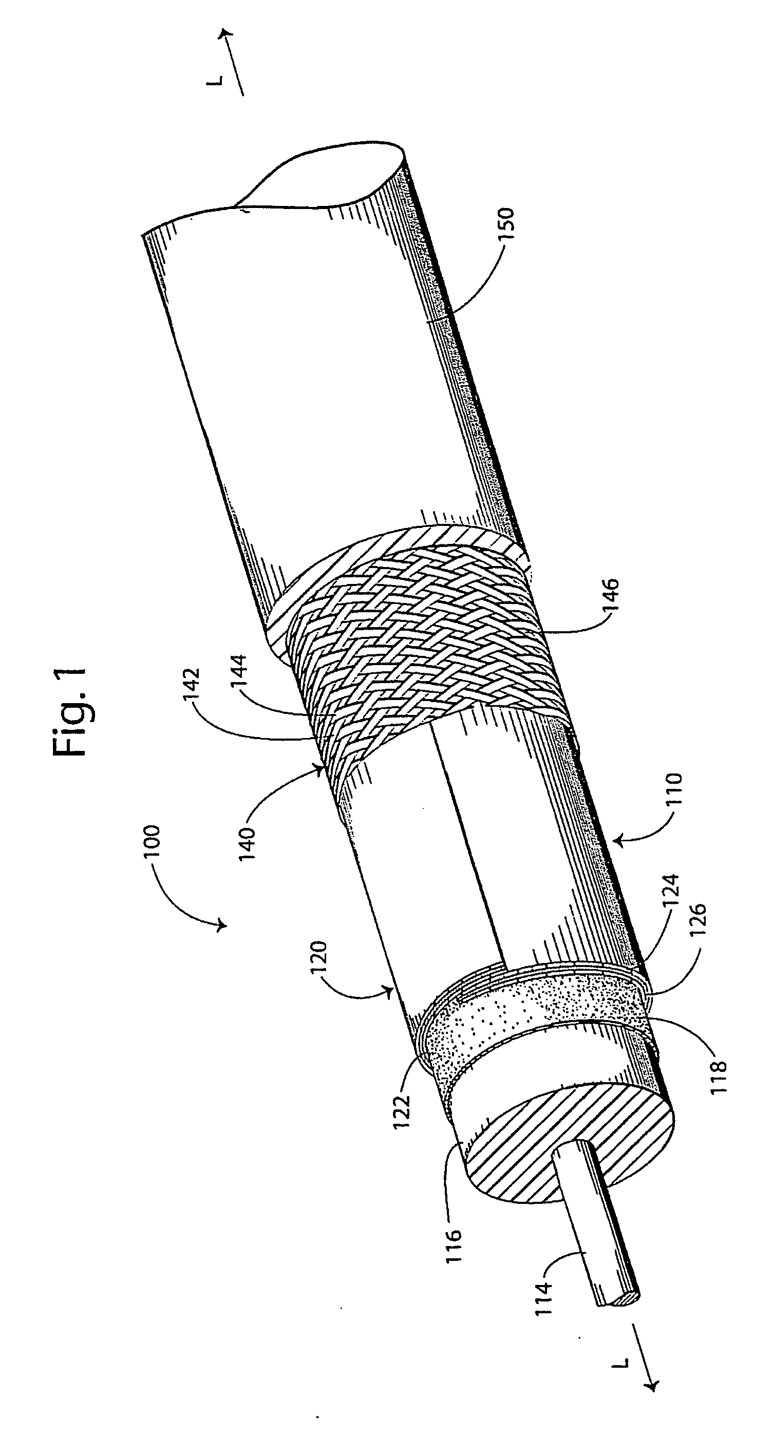
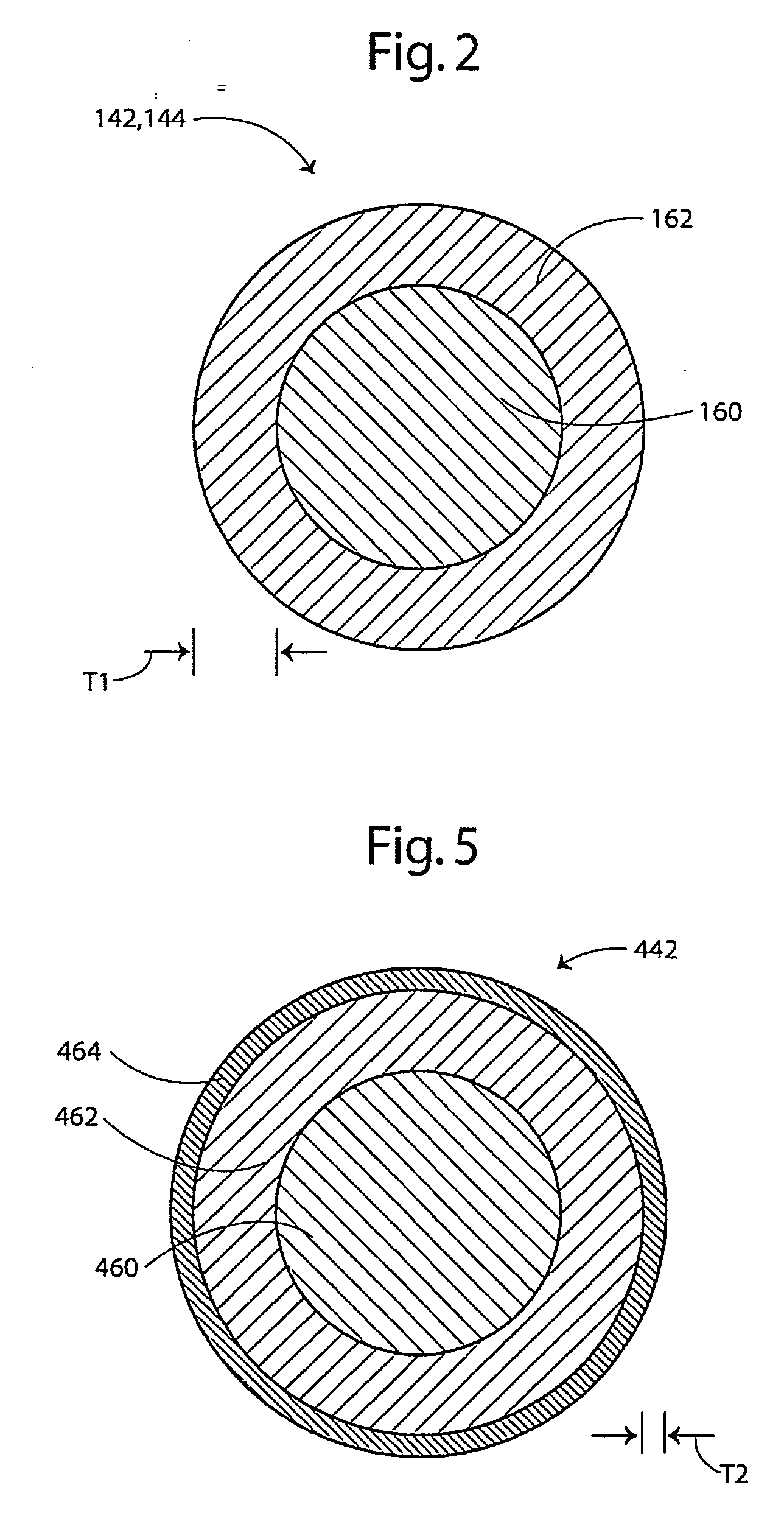
[0011] The present invention now is described more fully hereinafter with reference to the accompanying drawings, in which embodiments of the invention are shown. This invention may, however, be embodied in many different forms and should not be construed as limited to the embodiments set forth herein; rather, these embodiments are provided so that this disclosure will be thorough and complete, and will fully convey the scope of the invention to those skilled in the art.

[0012] Like numbers refer to like elements throughout. In the figures, the thickness of certain lines, layers, components, elements or features may be exaggerated for clarity. Broken lines illustrate optional features or operations unless specified otherwise.

[0013] The terminology used herein is for the purpose of describing particular embodiments only and is not intended to be limiting of the invention. As used herein, the singular forms “a”, “an” and “the” are intended to include the plural forms as well, unless ...


PUM

PropertyMeasurementUnit
volume percentaaaaaaaaaa
diameteraaaaaaaaaa

Abstract

A shielded electrical transmission cable includes an elongate inner conductor and an elongate shield member surrounding the inner conductor. The shield member is formed of at least one copper clad aluminum shield wire including a core including aluminum and a cladding surrounding the core and including copper.

Description

FIELD OF THE INVENTION [0001] The present invention relates to electrical transmission cables and, more particularly, to shielded electrical transmission cables. BACKGROUND OF THE INVENTION [0002] Electrical transmission cables such as communications cables often include one or more electrical conductors that serve as shield members to shield the cable from electromagnetic interference (EMI) and / or radio frequency interference (RFI). These conductors may also serve as signal conductors. A shield member may take the form of a plurality of fine gauge wires braided or served (i.e., wound) over a cable. It is known to use copper wires or, alternatively, aluminum wires. Copper may be advantageous because it produces relatively lower volume resistivity, lower transfer impedance, and lower signal loss in radio frequency cables as compared to aluminum. Also, copper may prevent galvanic reaction with an adjacent copper shielding tape. However, copper is significantly heavier and more costly ...

Claims


Application Information

Patent Timeline
Patent Type & Authority Applications(United States)
IPC IPC(8): H01B7/18
CPCH01B11/1008H01B11/1817H01B11/1033
Inventor STEVENS, RANDALL DEAN
Owner COMMSCOPE INC
Why Eureka
Try Eureka