Flush handle latch mechanism

a latch mechanism and handle technology, applied in the direction of mechanical devices, construction fastening devices, fastening means, etc., can solve the problems of increasing the complexity and cost of the manufacturing process, the latch may be relatively easily forced to a fully open position, and the possibility of securely closing

Inactive Publication Date: 2006-11-16
YONG TENG LONG
View PDF23 Cites 44 Cited by
  • Summary
  • Abstract
  • Description
  • Claims
  • Application Information

AI Technical Summary

Problems solved by technology

These problems and drawbacks include the use of many parts and often complicated combinations of motions between the parts to provide open and closed latch positions that may be actuated from either side of the door, thereby tending to increase the complexity and cost of the manufacturing process.
Additionally, it is often not possible to securely close the door, or other closure device, on which the latching mechanism is installed or mounted when there is a gap of more than a few millimeters between the door and the frame into which the latch bolt seats, so that the latch may relatively easily be forced to a fully open position.

Method used


Image

  • Flush handle latch mechanism
  • Flush handle latch mechanism
  • Flush handle latch mechanism

Examples


Embodiment Construction

Preferred Embodiment of the Latch Mechanism

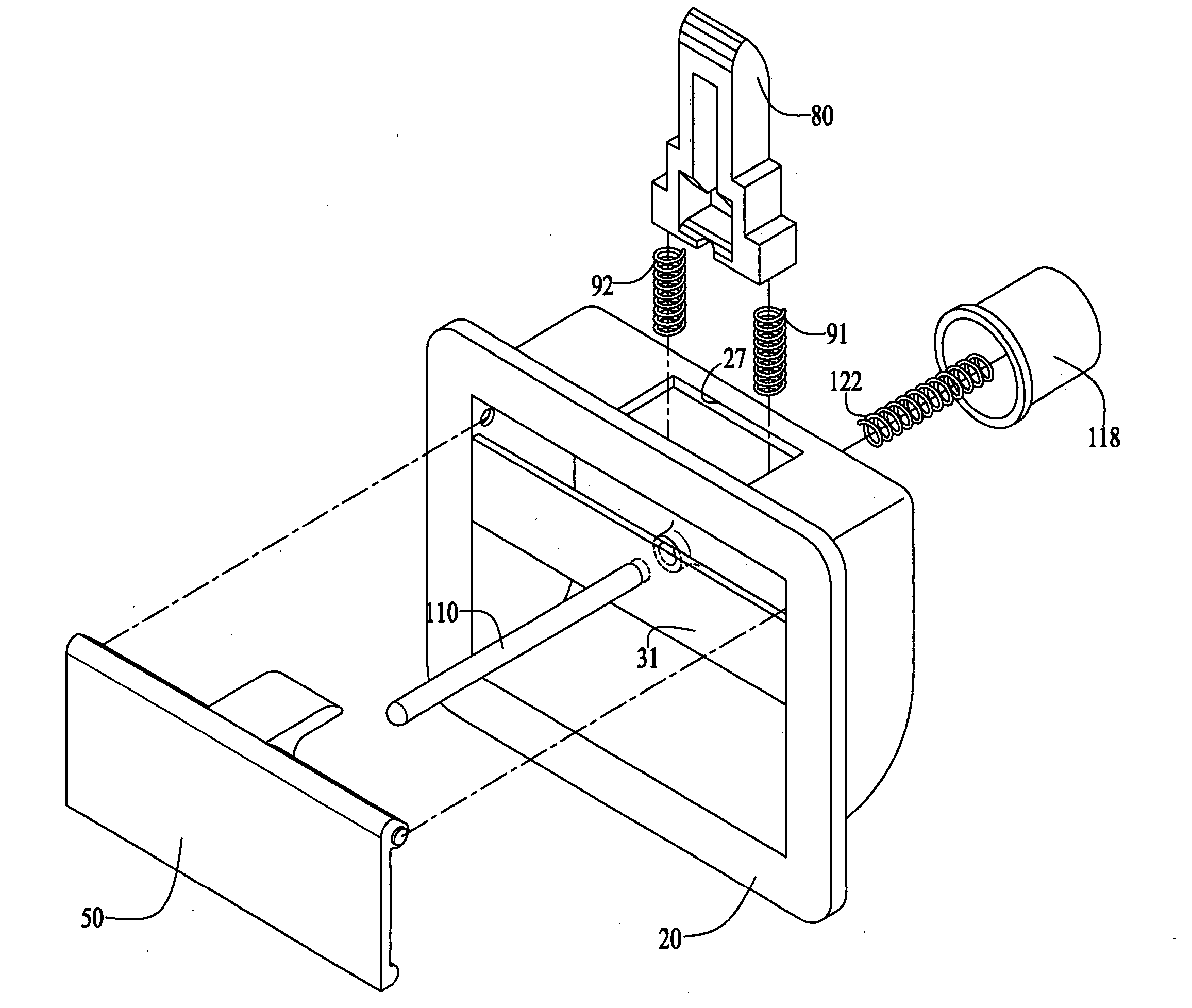
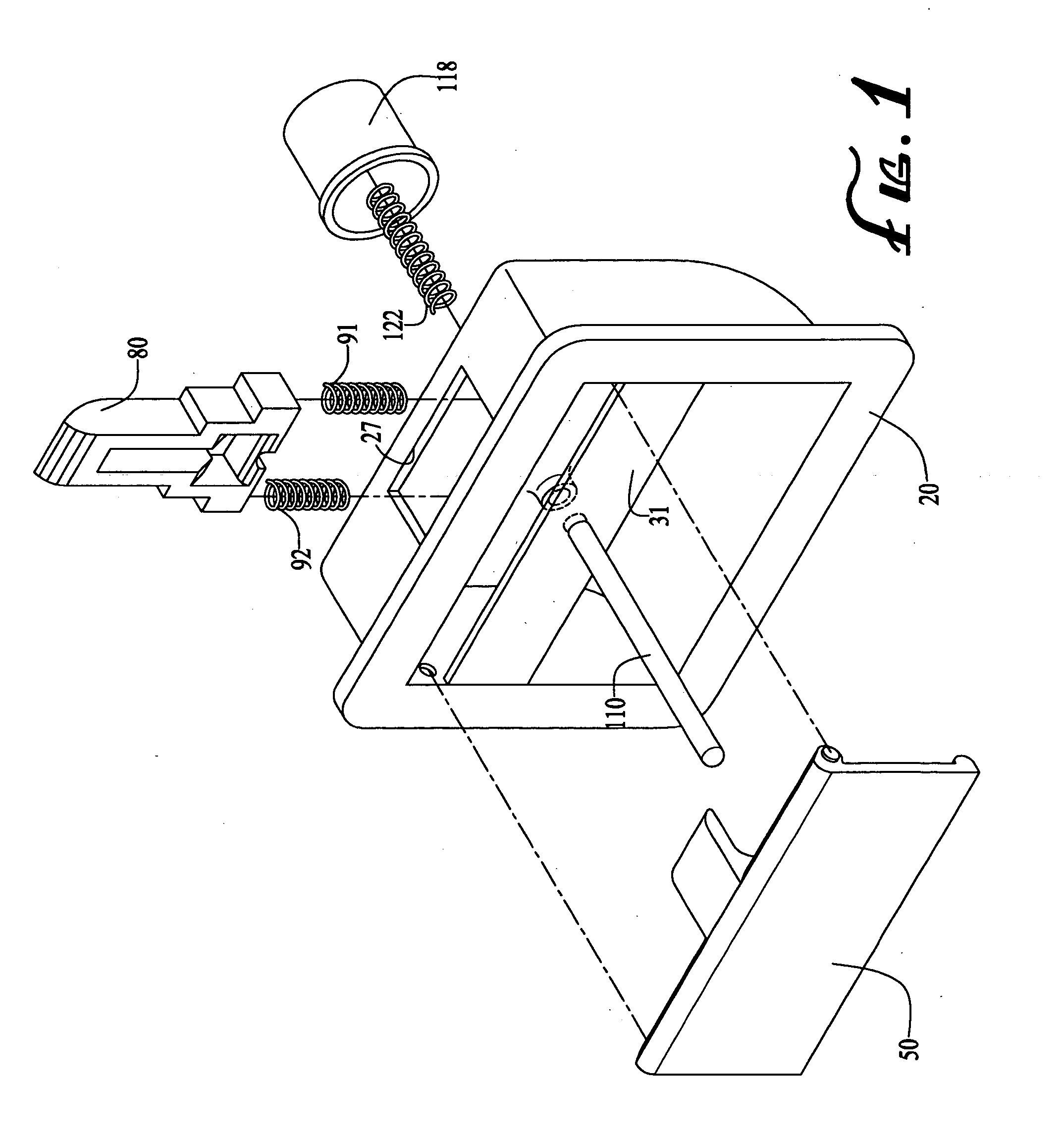
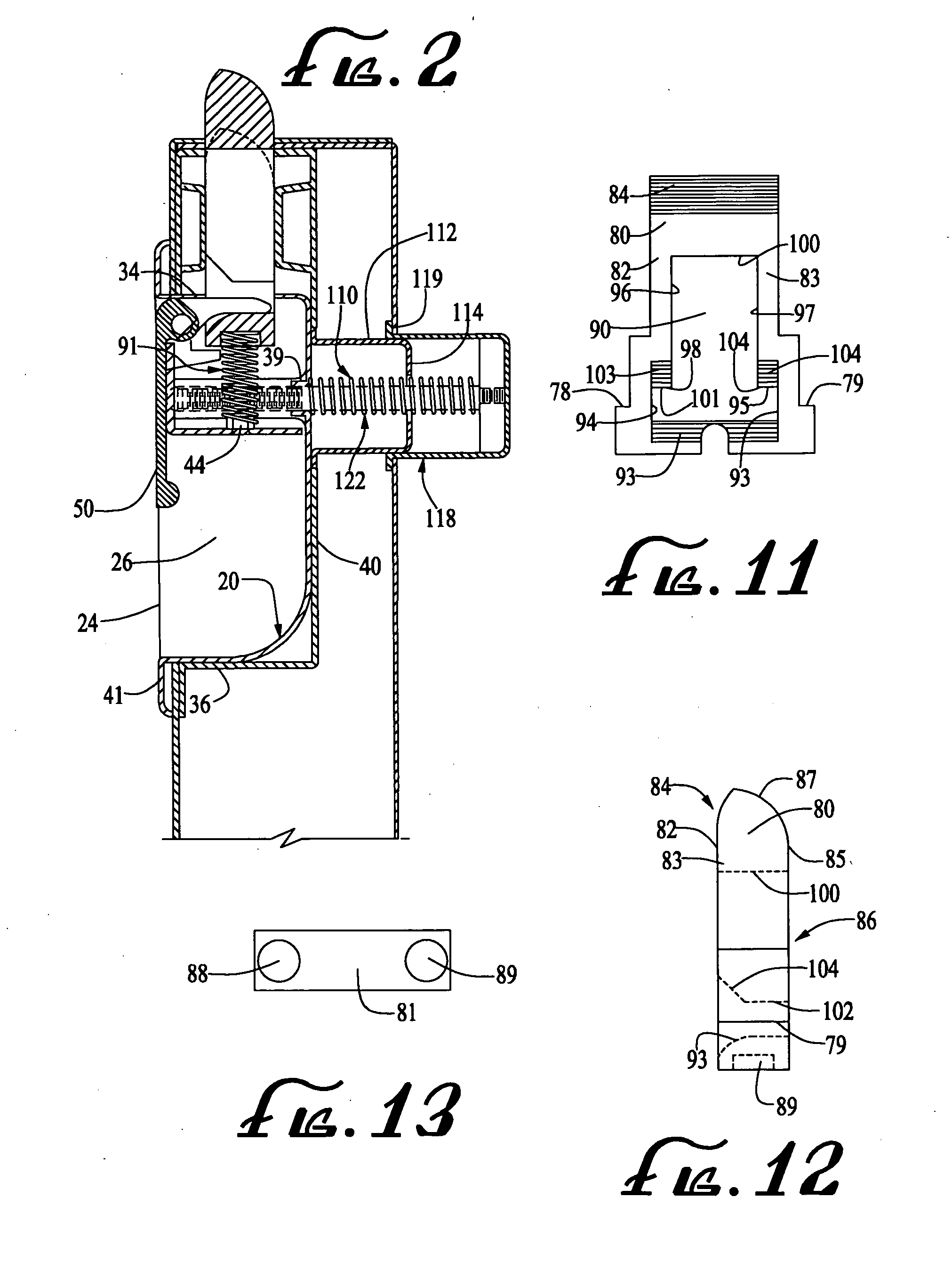
[0018] With reference to FIGS. 1-13, a latch assembly mechanism (10) including a housing (20) having a height, a width and a depth formed of an essentially rigid impact resistant and corrosion resistant material such as a polymer or metal, and having a housing wall (22) which may vary in thickness on the order, preferably, of a few millimeters. It is preferred that the housing be made of high impact polymeric material, metal or other material having rigidity and strength sufficient to be used in this field. The housing (20) includes a front side (24) having a front surface (41) in which a housing cavity (26) is formed, and a back side (28). Front side (24) includes rim (30) which forms a lip extending peripherally outward around housing cavity (26). Also, included in front side (24) of housing (20) is cavity floor (32), having cavity floor surface (29), and cavity walls (33), (34), (35) and (36) joining with and surrounding cavity floor (...


PUM


Abstract

The present invention provides a latch mechanism or assembly of the type commonly used on doors and on commercial cabinets and cases, and the like, that is simple to manufacture and has relatively few parts. The present invention provides a door, lid, gate, hatch, cover or other closure device latch mechanism or assembly for retaining a linearly operable bolt element securely by a striker or receiver element that is releasable from either side of the latch by operation of a rotary mechanism actuated by a flush handle on one side or a push button or push cap on the opposite side. It is emphasized that this abstract is provided to comply with the rules requiring an abstract that will allow a searcher or other reader to quickly ascertain the subject matter of the technical disclosure. It is submitted with the understanding that it will not be used to interpret or limit the scope of the claims.

Description

FIELD OF INVENTION [0001] The present invention is directed to a latch mechanism or assembly of the type commonly used on doors and on commercial cabinets and cases, and the like. The present invention provides a door, lid, gate, hatch, cover or other closure device latch mechanism or assembly for retaining a linearly operable bolt element securely by a striker or receiver element that is releasable from either side of the latch by operation of a rotary mechanism actuated by a flush handle on one side or a push button or push cap on the opposite side. [0002] Conventional locks and latch assemblies of the kind commonly used in the above described applications have exhibited a number of problems and drawbacks which the present invention is intended to improve upon. These problems and drawbacks include the use of many parts and often complicated combinations of motions between the parts to provide open and closed latch positions that may be actuated from either side of the door, thereb...

Claims


Application Information

Patent Timeline
Patent Type & Authority Applications(United States)
IPC IPC(8): E05C1/12
CPCE05C1/145E05C1/14Y10T292/0994
Inventor YONG, TENG-LONG
Owner YONG TENG LONG
Why Eureka
Try Eureka