
Systems and methods for order-picking

a system and method technology, applied in the field of order-picking, can solve the problems of limited success or ineffectiveness solutions suffering from one or more handicaps, and limited success or failure of rfid technology in order-picking applications

Active Publication Date: 2006-11-16
EMS TECHNOLOGIES
View PDF33 Cites 96 Cited by
  • Summary
  • Abstract
  • Description
  • Claims
  • Application Information

AI Technical Summary

Benefits of technology

[0014] In one exemplary embodiment in accordance with the invention, an order-picking system includes a picking cart having a radio frequency (RF) antenna arranged above an object-stacking surface of the picking cart. The order-picking system further includes a radio frequency identification (RFID) tag reader coupled to the RF antenna. The RFID tag reader is configured to identify a first RFID tag attached to a first tagged object placed on the picking cart and further configured to eliminate identification of a second RFID tag attached to a second tagged object located outside a perimeter of the object-stacking surface of the picking cart.

Problems solved by technology

Though RFID technology has been successfully incorporated into certain warehouse applications, it is unfortunate that there are several other warehouse applications in which it has met with limited success or has proven ineffective.
Specifically, RFID technology has met with limited success in order-picking applications.
Many of the proposed solutions suffer from one or more handicaps.
Unfortunately, when tagged objects, which are typically inhomogeneous in the nature of their contents, are stacked together, the RF energy may be hampered from reaching some of the passive RFID tags, thereby preventing successful tag operation.
In certain cases, RF energy is completely blocked from reaching some RFID tags when the tagged objects are encased inside RF-unfriendly material such as metal boxes or aluminum foil.
As a result of this shortcoming, the x-raying process fails to successfully and consistently identify all the individual RFID tags all the time.
Additionally, even if the RFID tag reader is able to successfully establish RFID communication with each and every RFID tag, the x-raying process still proves operationally inefficient when an object that is not on the order-picking inventory list has been inadvertently placed on the vehicle.
Discovery of this wrongfully-picked object by the portal-mounted RFID system leads to various undesirable manual operations such as dismantling of the stack, accurate identification and isolation of the individual object, identification of the shelf from which the object was picked, re-stocking of the object on the shelf, and re-verification of the rectified stack one more time.
Obviously, such manual operations lead to loss of time and money.
Unfortunately, this method often generates undesirable tag readings because the RFID tag reader not only reads the tag on the picked object but also generates readings from tags on other objects that have to remain shelved on shelves nearby.
Furthermore, this system suffers form the additional handicap that multiple RFID tag readers may be necessary to provide adequate coverage over a large number of shelves.
Unfortunately, this implementation also proves inadequate because of undesirable reading of tags on unpicked objects located outside the vehicle.
Unfortunately, the radiation pattern, coupled with other limitations associated with prior art RF antennas, has generally proven inadequate in eliminating undesirable reads of RFID tags located outside the vehicle.
Furthermore, this solution still suffers from the tag reading problems encountered when inhomogeneous objects are stacked together, more so when the objects are encased inside RF-unfriendly material.
In summary, based on the above-mentioned handicaps of existing RFID systems, an unaddressed need exists in the industry to overcome such deficiencies and inadequacies.

Method used


Image

  • Systems and methods for order-picking
  • Systems and methods for order-picking
  • Systems and methods for order-picking

Examples


Embodiment Construction

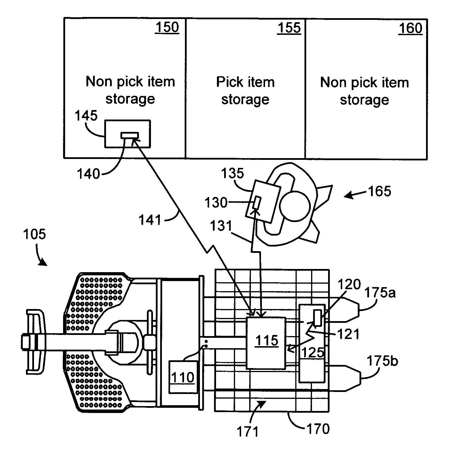
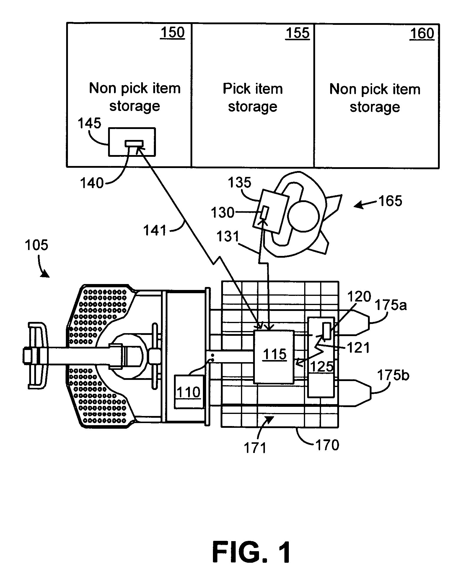
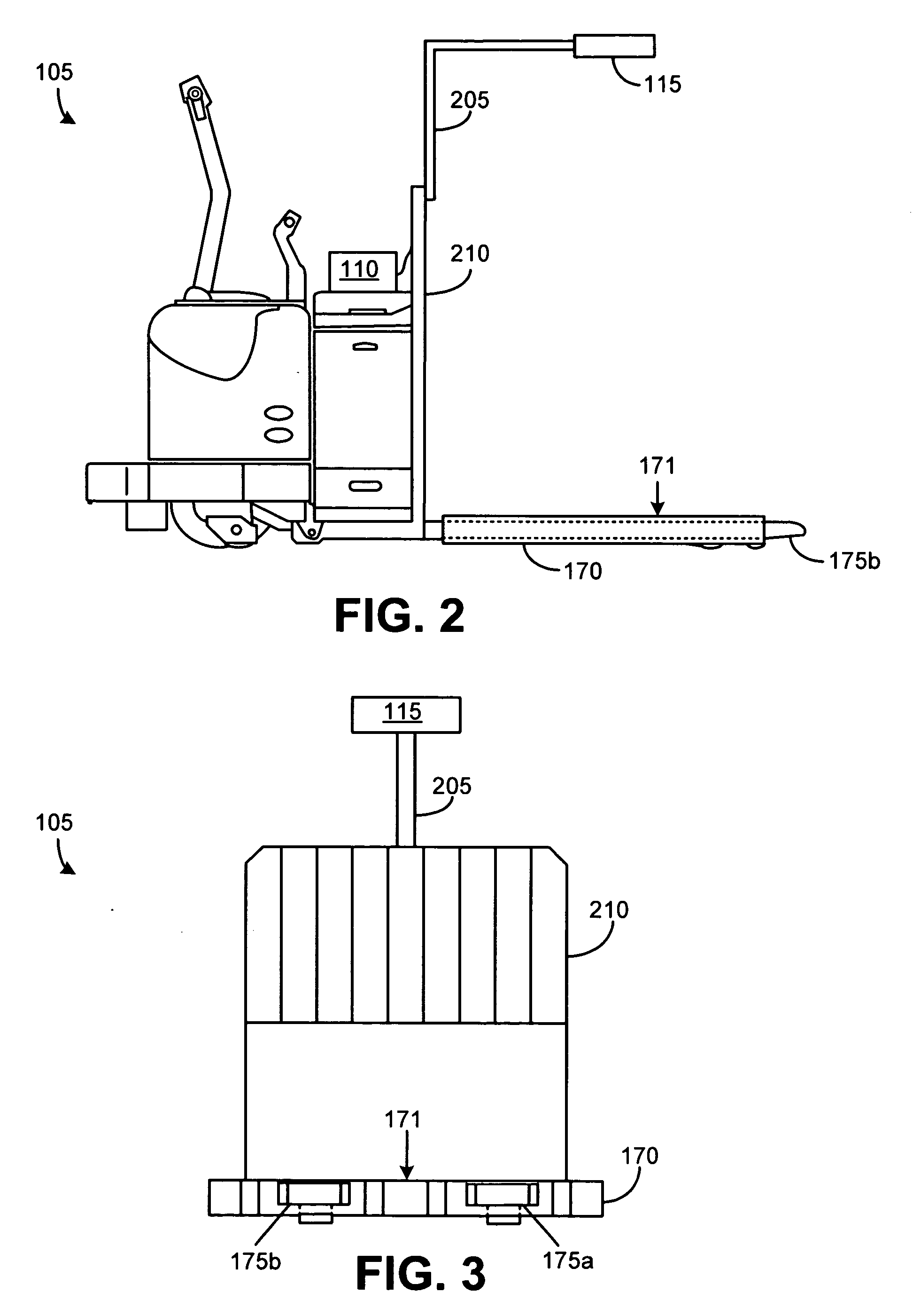
[0038] The various embodiments described below in accordance with the invention generally describe alternative features of a radio frequency identification (RFID) system mounted on a picking cart and further describe alternative methods for order picking.

[0039] It will be understood that various terms such as “picking cart,”“ID code,” and “order-picking” that are used in this disclosure should be interpreted in a broad sense and are not intended to be limited by the exemplary embodiments described herein.

[0040] As a general guideline, the term “picking cart” refers to any vehicle that is used to transport picked items. Some non-exhaustive examples of picking carts include a lift truck, a motorized pallet truck, a hand pallet truck, a shopping cart, a trailer, and a flatbed attached to a motorized vehicle.

[0041] The term “ID code,” which is used herein interchangeably with the term “ID data,” is intended to be interpreted as a generic term indicative of various types of identifica...


PUM


Abstract

In one exemplary embodiment in accordance with the invention, an order-picking system includes a picking cart having a radio frequency (RF) antenna arranged above an object-stacking surface of the picking cart. The order-picking system further includes a radio frequency identification (RFID) tag reader coupled to the RF antenna. The RFID tag reader is configured to identify a first RFID tag attached to a first tagged object placed on the picking cart and further configured to eliminate identification of a second RFID tag attached to a second tagged object located outside a perimeter of the object-stacking surface of the picking cart.

Description

CROSS REFERENCE TO RELATED APPLICATIONS [0001] This application claims priority under 35 U.S.C. § 119(e) from U.S. Provisional Patent Application Nos. 60 / 680,925, filed on May 13, 2005, and 60 / 718,947, filed on Sep. 20, 2005, both of which are incorporated herein by reference.STATEMENT REGARDING SPONSORED RESEARCH OR DEVELOPMENT [0002] Not Applicable. REFERENCE TO SEQUENCE LISTING [0003] Not Applicable. DESCRIPTION OF THE RELATED ART [0004] One among various processes associated with order fulfillment is termed “order-picking.” Order-picking generally refers to the process wherein a person uses an inventory list to identify and pick up multiple objects that are stored at various locations of a store or a warehouse. The process may be described in further detail using a warehouse order-picking process as an example. [0005] In the warehouse, an operator typically uses a suitable vehicle, such as a pallet truck or a lift truck, to drive down various aisles between shelves, stopping at ...

Claims


Application Information

Patent Timeline
Patent Type & Authority Applications(United States)
IPC IPC(8): G08B13/14
CPCB62B3/06B62B5/0096B66F9/0755B66F9/12G06K7/0008G06K7/10079H01Q13/22G06K2017/0051G06Q10/087H01Q1/22H01Q1/2216H01Q9/0421G06K7/10336
Inventor ROEDER, WILLIAM H.RUNYON, DONALD L.SORENSON, RICHARD W. JR.CLOTT, MICHAEL SAYRE
Owner EMS TECHNOLOGIES
Features
  • Generate Ideas
  • Intellectual Property
  • Life Sciences
  • Materials
  • Tech Scout
  • Unparalleled Data Quality
  • Higher Quality Content
  • 60% Fewer Hallucinations
Learn More