


Quick Research
Generate reliable direction feasibility study reports for your R&D in just a few steps.

Technical Q&A
Discover and master advanced knowledge NOW. Basics, ideas, possibilities, all at once.

Find Solutions
As an expert in R&D theories, this can generate solutions to your technical problems instantly.

Evaluate Feasibility
Analyze your overall solution with one click, know your potential R&D risks in advance.

Monitor Landscape
Get weekly tech updates, stay abreast of the latest tech innovations and key insights.
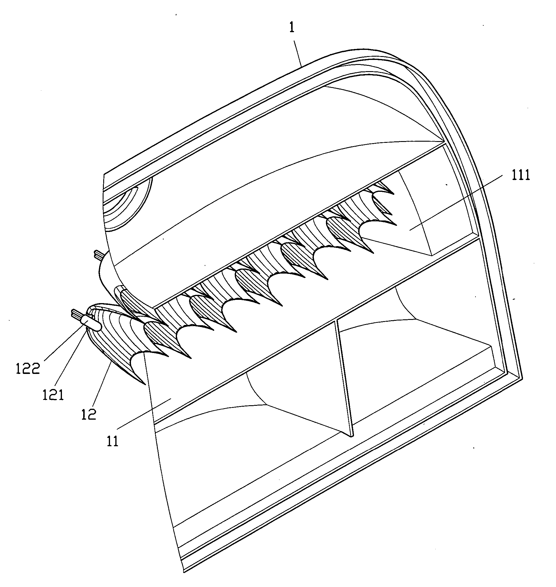
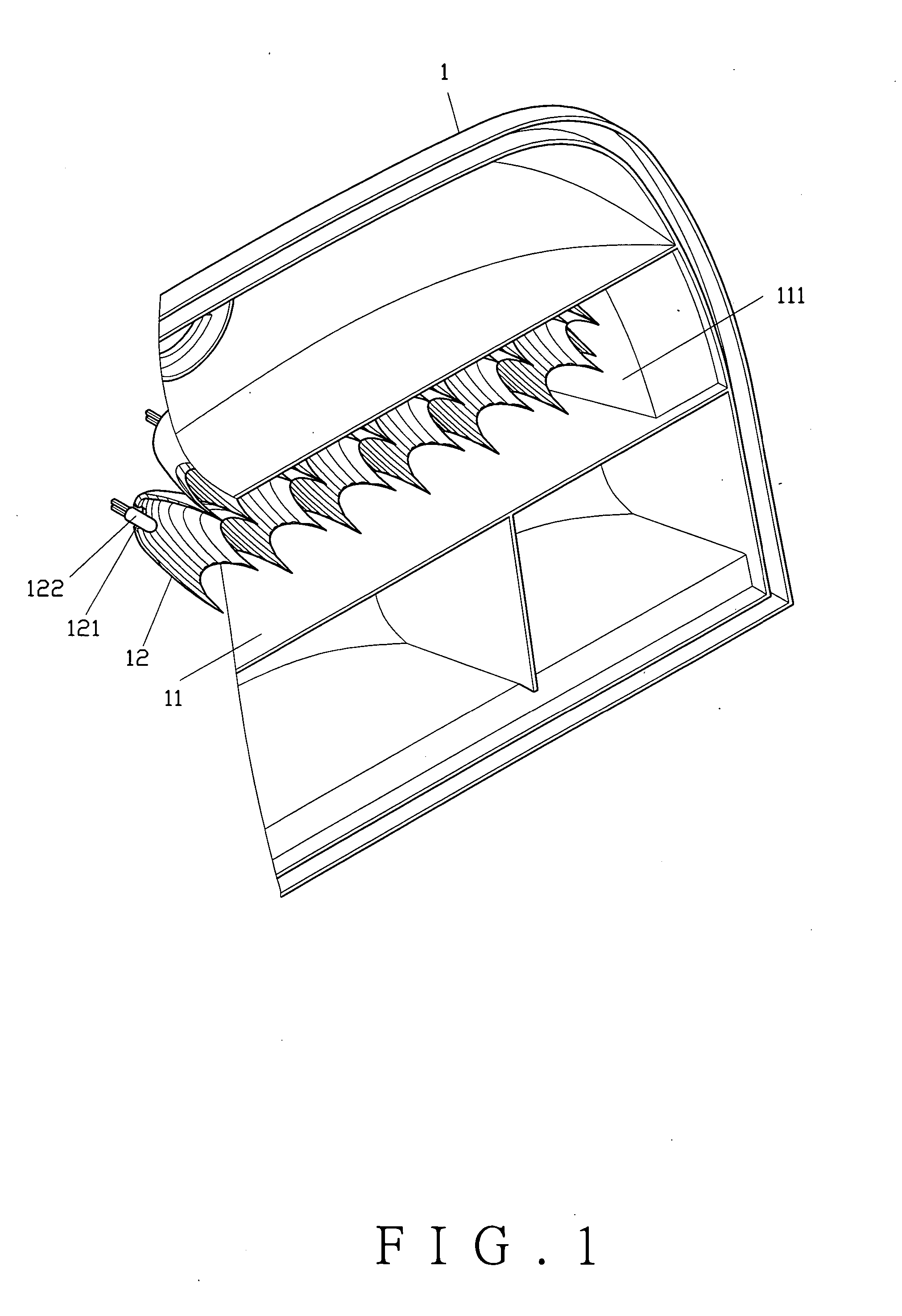
Taillight socket structure
a technology of taillight sockets and sockets, which is applied in the direction of signalling/lighting devices, vehicle components, lighting and heating apparatus, etc., can solve the problems of short life of light bulbs and high cost, and achieve the effect of increasing the lighting effect and safe driving
- Summary
- Abstract
- Description
- Claims
- Application Information
AI Technical Summary
Benefits of technology
Problems solved by technology
Method used
Image

Examples
second embodiment
[0021] As shown in FIG. 3, the present invention comprises a conical bulb socket 12A having a plurality of circular refractors 124A. The circular refractors 124A are formed along an inner wall 123A from a bulb hole 121A of the conical bulb socket 12A.
third embodiment
[0022] As shown in FIG. 4, the present invention comprises a conical bulb socket 12B having a plurality of non-flat refractors 124B. The refractors 124B are formed along an inner wall 123B of the conical bulb socket 12B to be arranged in a crisscross pattern.
fourth embodiment
[0023] As shown in FIG. 5, the present invention comprises a conical bulb socket 12C having a plurality of non-flat refractors 124C. The refractors 124 C are formed in an awl shape protruded from an inner wall 123C of the conical bulb socket 12C.
PUM
 Abstract
Description
Claims
Application Information
 - R&D Engineer
- R&D Manager
- IP Professional
- Industry Leading Data Capabilities
- Powerful AI technology
- Patent DNA Extraction
Browse by: Latest US Patents, China's latest patents, Technical Efficacy Thesaurus, Application Domain, Technology Topic, Popular Technical Reports.
© 2024 PatSnap. All rights reserved.Legal|Privacy policy|Modern Slavery Act Transparency Statement|Sitemap|About US| Contact US: help@patsnap.com