Methods and devices for discovering the topology of large multi-subnet LANs

a multi-subnet lan and topology technology, applied in the field of large multi-subnet lan topology discovery methods and devices, can solve the problems of large and complex systems of enterprise networks, difficult to maintain accurate descriptions of network topology without automatic topology discovery tools, and high computational complexity, etc., to achieve high probability, simple, efficient and practical mechanisms

Inactive Publication Date: 2006-11-16
LUCENT TECH INC
View PDF7 Cites 67 Cited by
  • Summary
  • Abstract
  • Description
  • Claims
  • Application Information

AI Technical Summary

Benefits of technology

[0005] We have recognized that the topology of large, heterogeneous Ethernet LANs that comprise multiple subnets as well as “dumb” or uncooperative elements, may be discovered by relying on MIB information. Unlike other existing solutions that require high computational complexity, the methods and devices of the present invention provide for simple, efficient and practical mechanisms for discovering a network's physical topology with a very high probability.

Problems solved by technology

So-called enterprise networks are typically large and complex systems comprising hundreds or thousands of network elements (e.g., switches) from different vendors.
Their complexity poses a challenge to network administrators who must ensure that such networks are managed effectively.
Because these changes occur so often, maintaining an accurate description of a network's topology is very difficult without the aid of automatic topology discovery tools.
It is difficult to obtain topological information.
Though this information is sufficient to determine a layer-3 topology, it fails to capture the complex interconnections making up a Ethernet Local Area Network (LAN); the interconnections and subnets that underlie and make up the logical links of layer-3.
This complicates the discovery of the underlying physical topology of a network that is made up of multiple subnets.

Method used


Image

  • Methods and devices for discovering the topology of large multi-subnet LANs
  • Methods and devices for discovering the topology of large multi-subnet LANs
  • Methods and devices for discovering the topology of large multi-subnet LANs

Examples


example 1

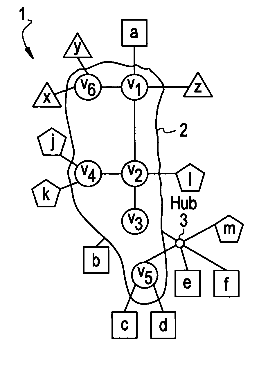
[0027]FIG. 1(a) depicts an example of a network 1 with switches 2 labeled V1-V6, one hub 3 and hosts labeled a-f, j-m, and x-z. The hosts are divided into three disjoint subnets; N1={a,b,c,d,e,f}, N2={j,k,l,m} and N3={x,y,z}, where each switch is solely included in a separate subnet. The connecting trees of N1, N2 and N3 are presented in FIGS. 1(b)-(d), respectively.

[0028] Let Nν⊂Ndenote the collection of subnets containing node νεV in their connecting trees. (Recall that a switch may serve hosts in different subnets.) Essentially, AFTs of ports of a given node ν contain node-reachability information, mainly, for the subnets in Nν. The AFTs of node ν may also contain the MAC addresses of other nodes as well. However, these AFTs entries are usually created from sporadic broadcast messages. Due to the aging process of AFT information, they are gradually removed from AFTs. Thus, in accordance with one embodiment of the present invention, the only AFT information utilized is that of th...

example 2

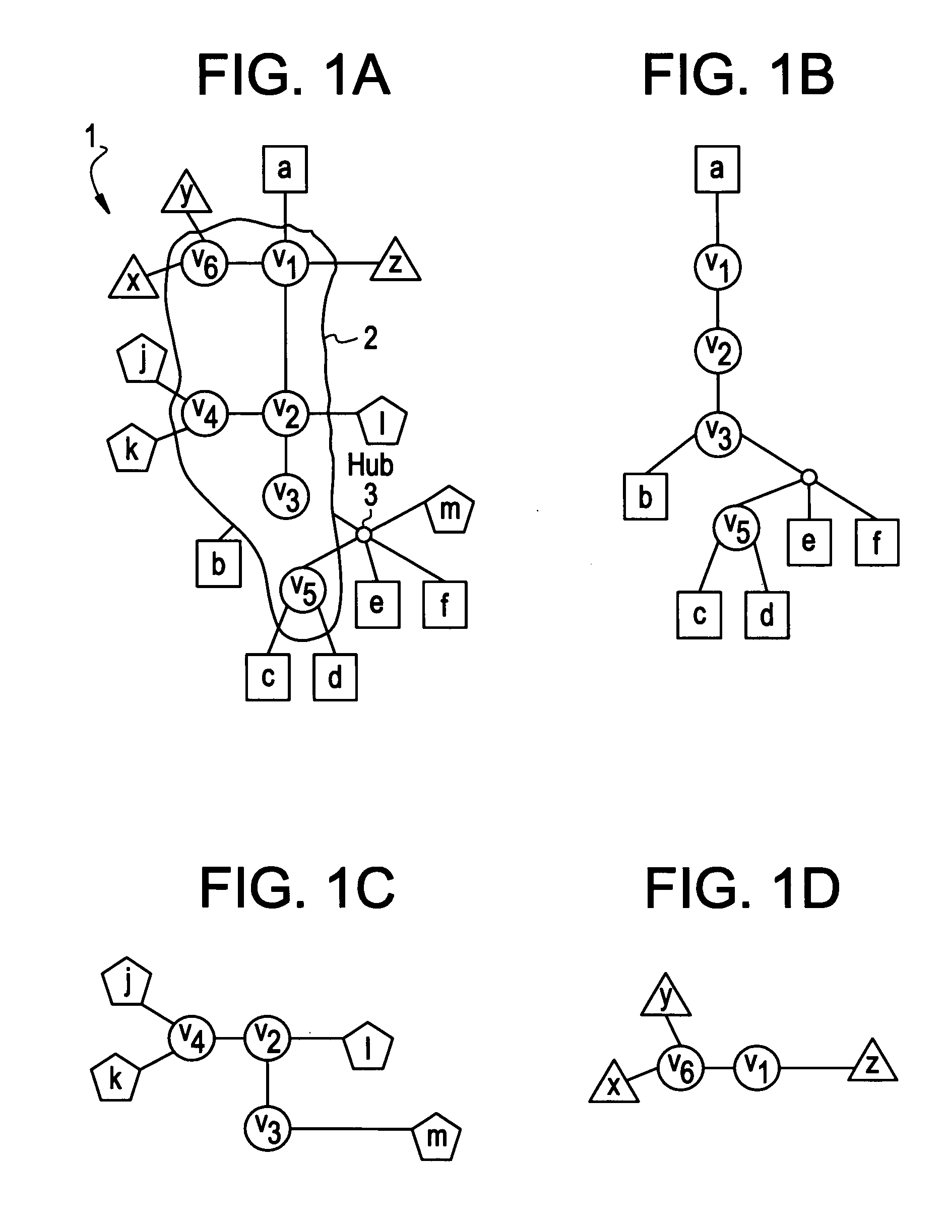
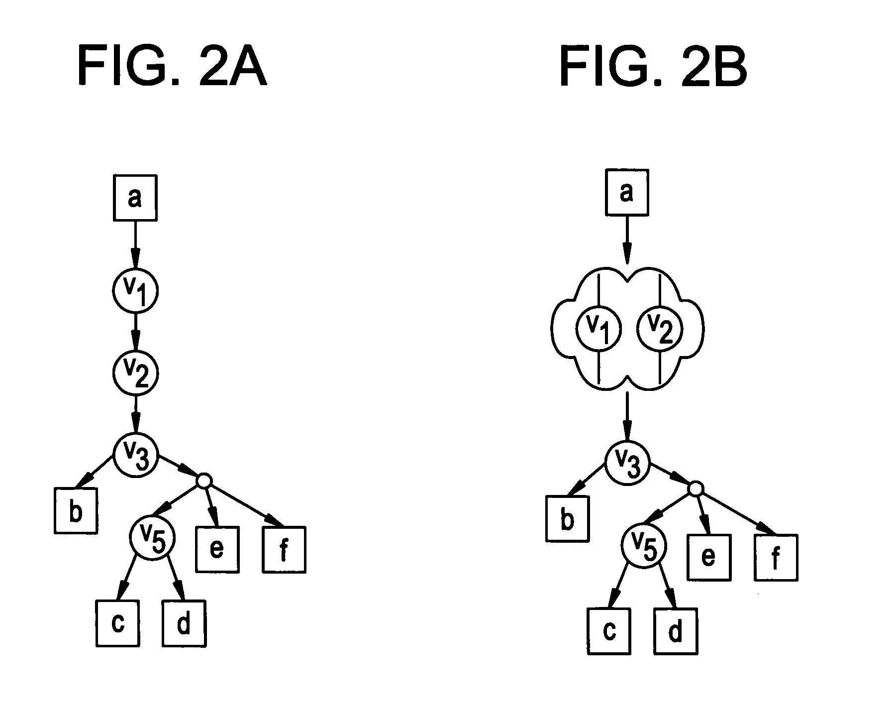
[0044]FIG. 2(a) depicts the connecting tree of subnet N1 while FIG. 2(b) depicts a corresponding skeleton-tree. It should be noted that FIG. 2(a) depicts a directed connecting tree rooted at node a. In some of the discussion which follows, such a tree may be used to illustrate a skeleton-tree creation step of the present invention. In addition, it may be seen that the skeleton tree of subnet N1 represents switches {ν1, ν2} having a single vertex.

[0045] We now introduce the details of a TD technique that may be used by an NMS to infer the topology of a given LAN in accordance with an embodiment of the present invention.

[0046] The set of subnets of a considered network may be denoted TNi (VNi, ENi), by N, and the connecting tree of every subnet NEN. In an embodiment of the present invention, an NMS or the like is operable to collect the required AFT information and then execute a topology discovery (TD) algorithm. The latter utilizes a skeleton-tree creation (STC) algorithm describe...

example 3

[0055] Consider three skeleton trees spanned by the subnets N1, N2 and N3. The skeleton trees of subnets N1 and N2 can be merged by an NMS using node ν3 as a common anchor. Consequently, nodes ν1 and ν2 appear as anchor nodes in a resulting skeleton-tree. Then, an NMS may merge the skeleton tree of both subnets, TN1∩N2, with the skeleton tree of subnet N3, where node ν1 is used as a common anchor. This merge operation yields an overall network topology.

[0056] Throughout our discussion above, we have made reference to a skeleton-tree creation (STC) technique or algorithm (i.e., method). This is a building block of the present invention.

[0057] In accordance with embodiments of the present invention, STC algorithms are based on properties of a connecting tree TN(VN, EN). First, a root-node rεN is selected for the connecting tree TN. It should be noted that the node r may be any node in N and may be completely independent of a root node used by a known spanning tree algorithm. For eac...


PUM


Abstract

The physical topology of large, heterogeneous Ethernet LANs that may include multiple subnets may be discovered utilizing Management Information Base (MIB) information. Topology discovery tools and network management systems are introduced to carry out the topological discovery methods, features and functions of the present invention.

Description

BACKGROUND OF THE INVENTION [0001] So-called enterprise networks are typically large and complex systems comprising hundreds or thousands of network elements (e.g., switches) from different vendors. Their complexity poses a challenge to network administrators who must ensure that such networks are managed effectively. To this end, maintaining an accurate and complete knowledge of a network's physical topology is a prerequisite to carrying out many critical network management tasks, including network diagnostics, resource management, event correlation, root cause analysis and server placement. [0002] Such knowledge necessarily includes knowledge of the actual physical connections between network elements in a network, connections that are frequently changing. Because these changes occur so often, maintaining an accurate description of a network's topology is very difficult without the aid of automatic topology discovery tools. [0003] It is difficult to obtain topological information....

Claims


Application Information

Patent Timeline
Patent Type & Authority Applications(United States)
IPC IPC(8): H04L12/28H04L12/56
CPCH04L41/12H04L12/462
Inventor BEJERANO, YIGAL
Owner LUCENT TECH INC
Why Eureka
Try Eureka