
Transcript apparatus

a technology of transcription apparatus and forming product, which is applied in the direction of photomechanical apparatus, applications, instruments, etc., can solve the problems of adversely difficult to perform the appropriate forming, and affecting the control of force pressing the die to the forming product, etc., to achieve simple and appropriate manner minimizing adverse effects

Inactive Publication Date: 2006-11-16
TOSHIBA MASCH CO LTD
View PDF19 Cites 10 Cited by
  • Summary
  • Abstract
  • Description
  • Claims
  • Application Information

AI Technical Summary

Benefits of technology

[0005] The present invention has been completed with the above issues in mind and has an object to provide a transcript apparatus that can perform the forming in a simple and appropriate fashion minimizing adverse affect arising from pressure variation in a vacuum-forming chamber.

Problems solved by technology

Therefore a pressure inside the vacuum-forming chamber fluctuates when the vacuum-forming chamber is depressurized, and this causes to vary load acting on the movable member in the moving direction.
Such force acts on a drive section of the movable member to adversely affect the control of force pressing the die to the forming product.
This makes it difficult to perform the appropriate forming.

Method used


Image

  • Transcript apparatus
  • Transcript apparatus
  • Transcript apparatus

Examples


Embodiment Construction

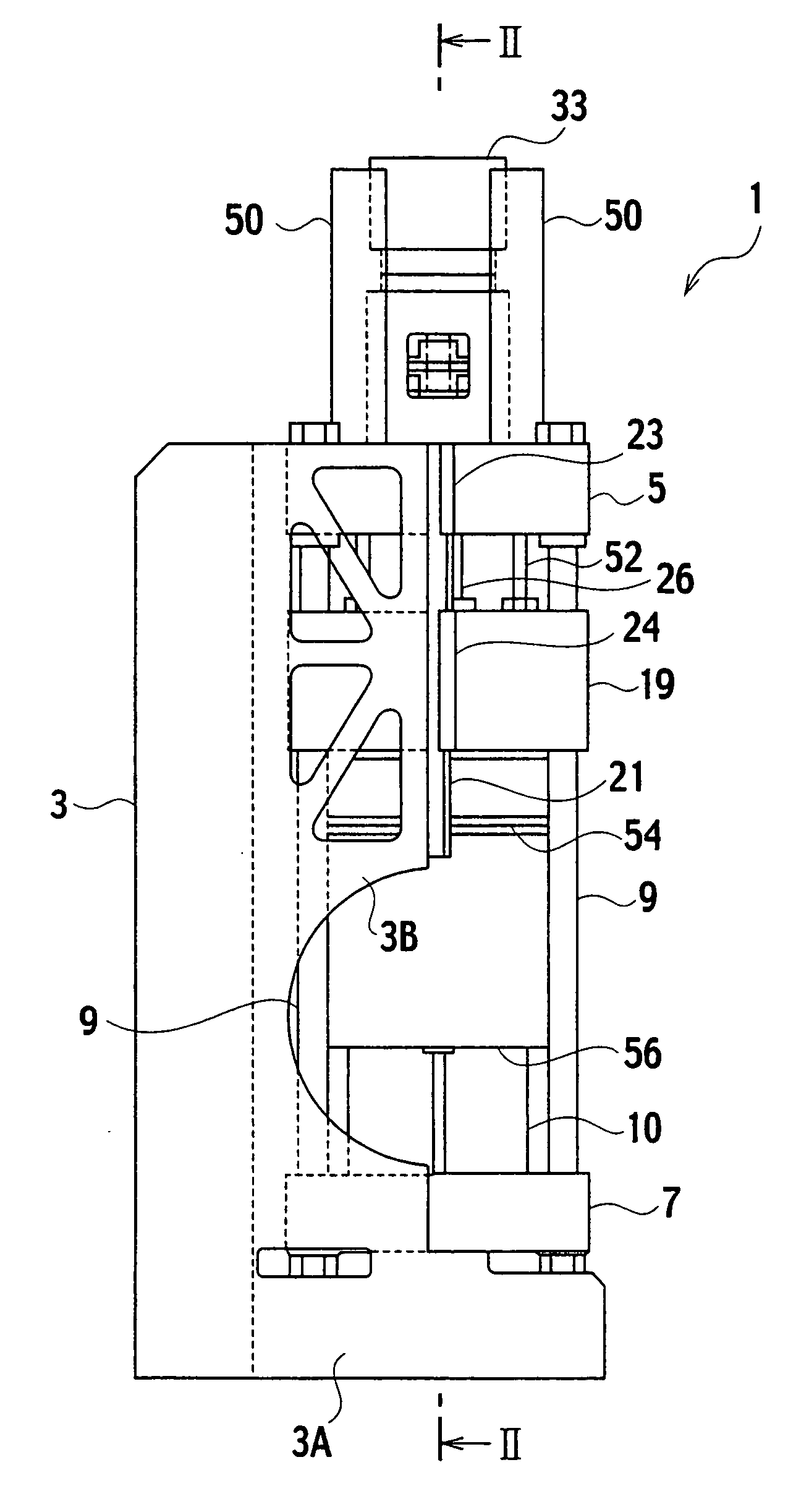
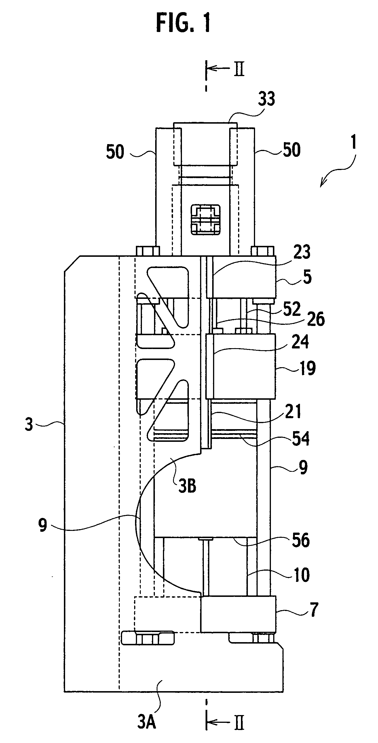
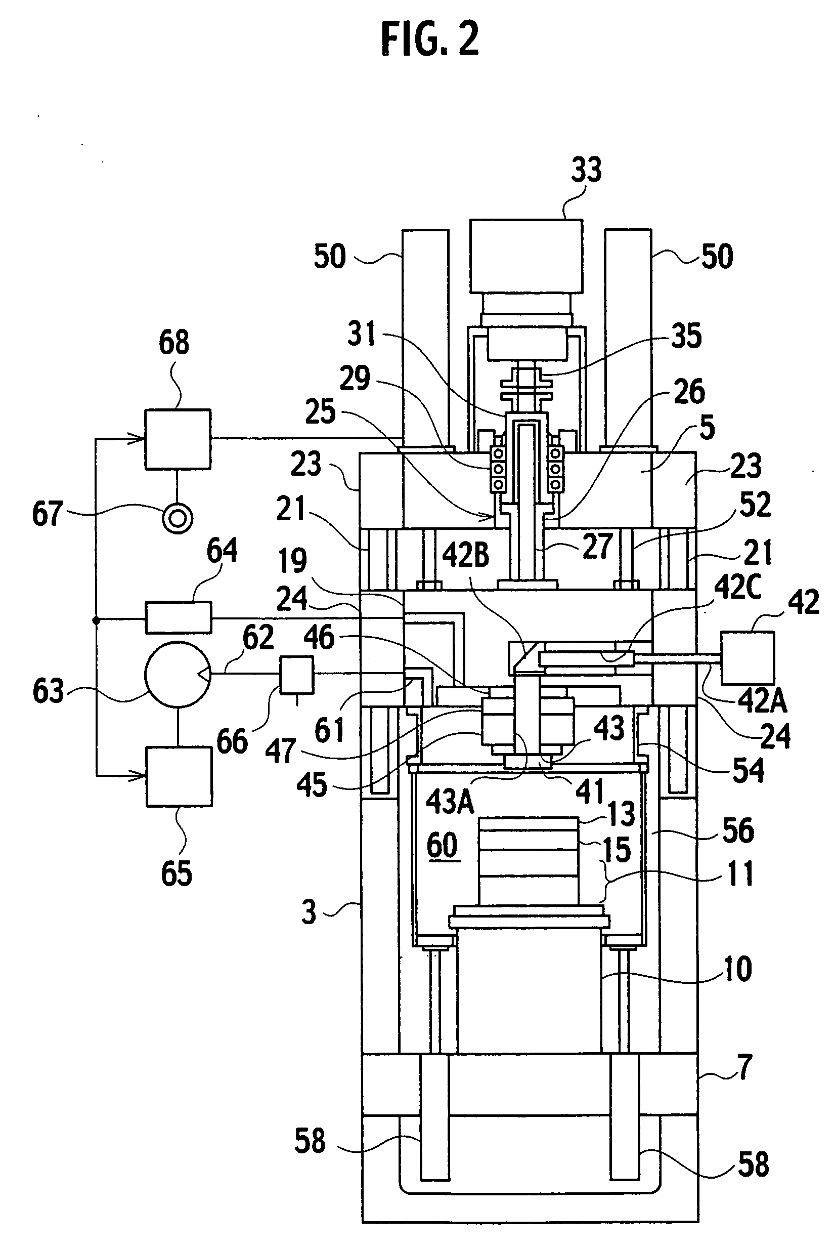
[0012] As shown in FIGS. 1 and 2, a transcript apparatus 1 of one embodiment according to the present invention includes: a body frame 3 having a generally L-shaped side shape; a square-shaped lower frame (base frame) 7 integrally mounted on a lower side of a frame support section 3A by which the lower frame 7 is supported; die bars 9 standing upright from four corners of the lower frame 7 in parallel to a vertical section of the body frame 3; a square-shaped upper frame (support frame) 5 located on upper ends of the die bars 9 for supporting a drive means; and a square-shaped movable body 19 supported on the die bars 9 to be movable in a direction along the die bars 9 (vertical direction) in a space between the upper frame 5 and the lower frame 7.

[0013] The body frame 3 has an upper area formed with a pair of guide frames 3B, 3B. The guide frames 3B, 3B protrudes forward (rightward in FIG. 1) such that their end faces reach positions substantially half of left and right side faces...


PUM

PropertyMeasurementUnit
Forceaaaaaaaaaa
Pressureaaaaaaaaaa

Abstract

A transcript apparatus has a vacuum-forming chamber 60 in which a transcription die 41 and a forming product 13 transcribed from the die 41 are disposed face to face with each other, a movable body 19 supporting one of the die 41 and the product 13 to allow the die 41 and the product 13 to be movable closer to or away from each other, a balance cylinder 50 placed in parallel to a moving direction of the movable body 19 and connected to the movable body 19 via a piston rod 52, a pressure detector 64 detecting a pressure inside the chamber 60, and a pressure control section 68 operative to control a pressure of working fluid supplied to the chamber 60 depending on an output from the pressure detector 64 to cancel fluctuation in load acting on the movable body 19 in the moving direction thereof.

Description

BACKGROUND OF THE INVENTION [0001] The present invention relates to transcript apparatuses wherein a finely engraved pattern formed on a surface of a die is transcribed onto a surface of a forming product using lithographic technology and, more particularly, to a transcript apparatus wherein a die and a forming product are disposed in a vacuum-forming chamber. [0002] Since transcript apparatuses of this kind often give rise to a forming defect because of air or inactive gas (as an forming atmosphere) shut into a space between a die and a forming product, a transcript apparatus disclosed in Japanese Patent Provisional Publication No. 2004-288784 allows a die and a forming product to be disposed in an openable and closable vacuum-forming chamber. SUMMARY OF THE INVENTION [0003] The transcript apparatus has a movable member movably that supports one of the die and the forming product, and a member that faces and brings into abutting engagement with the movable member. To move the die a...

Claims


Application Information

Patent Timeline
IPC IPC(8): B28B11/08B81C99/00
CPCB29C35/0888B29C2035/0827B29C59/026B29C59/02G03F7/0002
Inventor KOKUBO, MITSUNORIURUSHIBATA, KAZUNORIMATSUBAYASHI, HARUYUKI
Owner TOSHIBA MASCH CO LTD
Learn More