Control system for engine with auxiliary device and related engine control method

a technology of control system and engine, which is applied in the direction of electric generator control, electric control, machines/engines, etc., can solve the problems of adverse effects of operating parameter on engine torque control, detection of failure related to operating parameter, etc., to improve controllability, and minimize the adverse effect of failur

Inactive Publication Date: 2008-01-10
DENSO CORP
View PDF3 Cites 17 Cited by
  • Summary
  • Abstract
  • Description
  • Claims
  • Application Information

AI Technical Summary

Benefits of technology

[0030]With such an engine control method, the failure related to the operating parameter adversely affecting engine torque control is detected. Then, at a time instant when the failure is detected, the drive control of the auxiliary device is altered. This makes it possible to minimize the adverse affect given to the engine control. Thus, the auxiliary device can be driven while minimizing the adverse affect of the failure given to engine torque control. This enables the engine to operate in improved controllability to achieve high performance for driving the vehicle in a comfortable manner.

Problems solved by technology

With such a structure of the control system, the failure related to the operating parameter adversely affecting engine torque control is detected.

Method used


Image

  • Control system for engine with auxiliary device and related engine control method
  • Control system for engine with auxiliary device and related engine control method
  • Control system for engine with auxiliary device and related engine control method

Examples


first embodiment

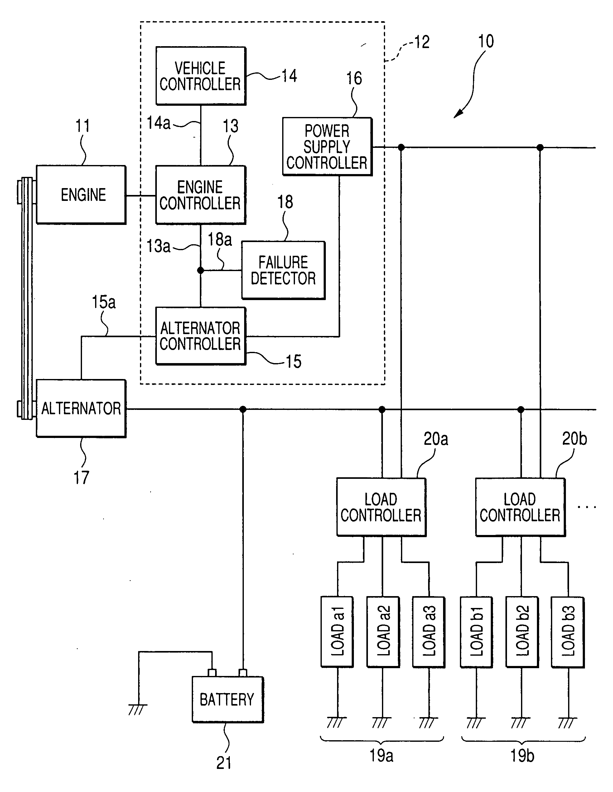
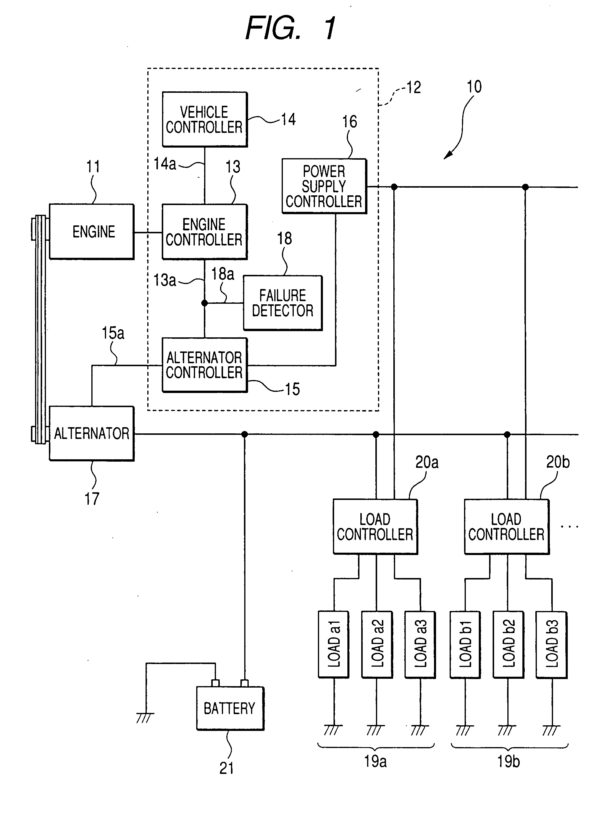
[0039]Now, an overall structure of an engine control system of a first embodiment according to the present invention will be described below in detail with reference to FIG. 1.

[0040]As shown in FIG. 1, the engine control system 10 is applied to an internal combustion engine 11 for a vehicle that includes various systems such as an air-intake system, a fuel injection system and an ignition system. The engine control system 10 includes a control device 12 for controlling the internal combustion engine 11 and an alternator 17 playing a role as an auxiliary device.

[0041]The engine control device 12 includes an engine controller 13 connected to the air-intake system, the fuel injection system and the ignition system of the engine 11 for controlling these component parts depending on a vehicle condition. The engine control device 12 includes, in addition to the engine controller 13, a vehicle controller 14, an alternator controller 15 playing a role as an auxiliary-device controller, a po...

second embodiment

[0092]With the engine control system 10 of the first embodiment mentioned above, the control mode is switched between the fixed voltage control mode and the gradual change control mode depending on the severity of the failure being detected with the failure detector 18. However, the control mode may be switched between the fixed voltage control mode and the gradual change control mode depending on the severity of the failure, detected with the failure detector 18, and the engine operating conditions.

[0093]An engine control system of a second embodiment implementing such a concept is described below with reference to FIG. 7 showing an alternator control routine to be used in the second embodiment. The engine control system of the second embodiment has the same structure as that achieved in the first embodiment except for the alternator control routine shown in FIG. 7 and, therefore, the same component parts as those of the engine control system of the first embodiment bear like refer...


PUM


Abstract

An engine control method and related engine control method are disclosed for an engine with an auxiliary device of a vehicle wherein auxiliary device control means controls a drive torque of the auxiliary device, engine control means executes an engine torque control to vary the output torque of the engine, and failure detecting means detects a failure giving an adversely affect to engine torque control executed with the engine control means. The auxiliary device control means alters a drive control mode of the auxiliary device in response to the failure detected with the failure detecting means. In preferred embodiment, the auxiliary device is driven in a collaborative control mode in the presence of an extremely mild failure, a fixed voltage control mode in the presence of a mild failure and a gradual change control mode in the presence of a fatal failure.

Description

CROSS REFERENCE TO RELATED APPLICATIONS[0001]This application is related to Japanese Patent Application No. 2006-186245, filed on Jul. 6, 2006, the content of which is hereby incorporated by reference.BACKGROUND OF THE INVENTION[0002]1. Technical Field of the Invention[0003]The present invention relates to control systems for engines with auxiliary devices and, more particularly, to a control system for an engine with an auxiliary device which has a function to control drive torque of an auxiliary device driven with output torque (hereinafter referred to as “engine torque”) of the engine.[0004]2. Description of the Related Art[0005]A modern vehicle is installed with various engine-driven auxiliary devices such as, for instance, an alternator, an air-conditioning compressor, a power steering compressor, a motor generator, a booster pump for raising a fuel pressure, and an oil pump, etc.[0006]These auxiliary devices are driven with engine torque. Therefore, as drive torque (that is, a...

Claims


Application Information

Patent Timeline
Patent Type & Authority Applications(United States)
IPC IPC(8): F02D29/00B60K25/00F02D29/02F02D29/04F02D29/06H02P9/04
CPCB60K25/00F02D41/021F02D41/1497Y02T10/40F02D2200/1004F02D2250/24F02D41/221
Inventor YAMASHITA, YUKIHIROOBAYASHI, KAZUYOSHITANI, KEISUKETANAKA, KATSUNORISHIMOYAMA, TAKESHIYAMAMOTO, NAOKI
Owner DENSO CORP
Why Eureka
Try Eureka