Fluid analyzer

Inactive Publication Date: 2005-09-08
HORIBA LTD
View PDF3 Cites 10 Cited by
  • Summary
  • Abstract
  • Description
  • Claims
  • Application Information

AI Technical Summary

Benefits of technology

[0012] The invention has been made in view of the aforesaid matter, and an object of the invention is to provide a cell for analyzing fluid and an analyzing apparatus using the cell which can improve the degree of freedom as to the arrangement of the cell, be disposed at a small space, obtain a sufficient optical length by a small amount of sample, does not require a large-sized light shielding mechanism nor an additional many constituent parts and can change the optical length easily.
[0013] Another object of the invention is to provide a fluid analyzer that not only can eliminate the use of the glass window members to simplify a structure and lower the manufacturing cost, but also can minimize adverse affect owing to air bubbles and fine particles in the sample liquid on incident and exit light to enable to measure normally and precisely even during continuous use over a long time.

Problems solved by technology

Further, the cell with the reflection structure therein has a problem that a precise and complicated reflection structure is required and a volume of the cell becomes larger in order to obtain a sufficient optical length due to the reflection.
Further, according to the conventional cell for analyzing fluid configured in the aforesaid manner, the volume of the cell is large since the cell is configured in a linear shape or the reflection structure is provided within the cell, so that the space for disposing the cell itself becomes large and much sample is required.
In addition, since the cell is required to be provided with the aforesaid additional mechanism, there arises a problem that the space for disposing the cell becomes further larger.
Further, according to the conventional cell, in the case of changing the cell length, the hardware (for example, the analyzing apparatus using the cell) is required to be changed entirely and so the cell length cannot be changed easily.
In other words, it is difficult to change the cell length by using only one housing.

Method used


Image

  • Fluid analyzer
  • Fluid analyzer
  • Fluid analyzer

Examples


fourth embodiment

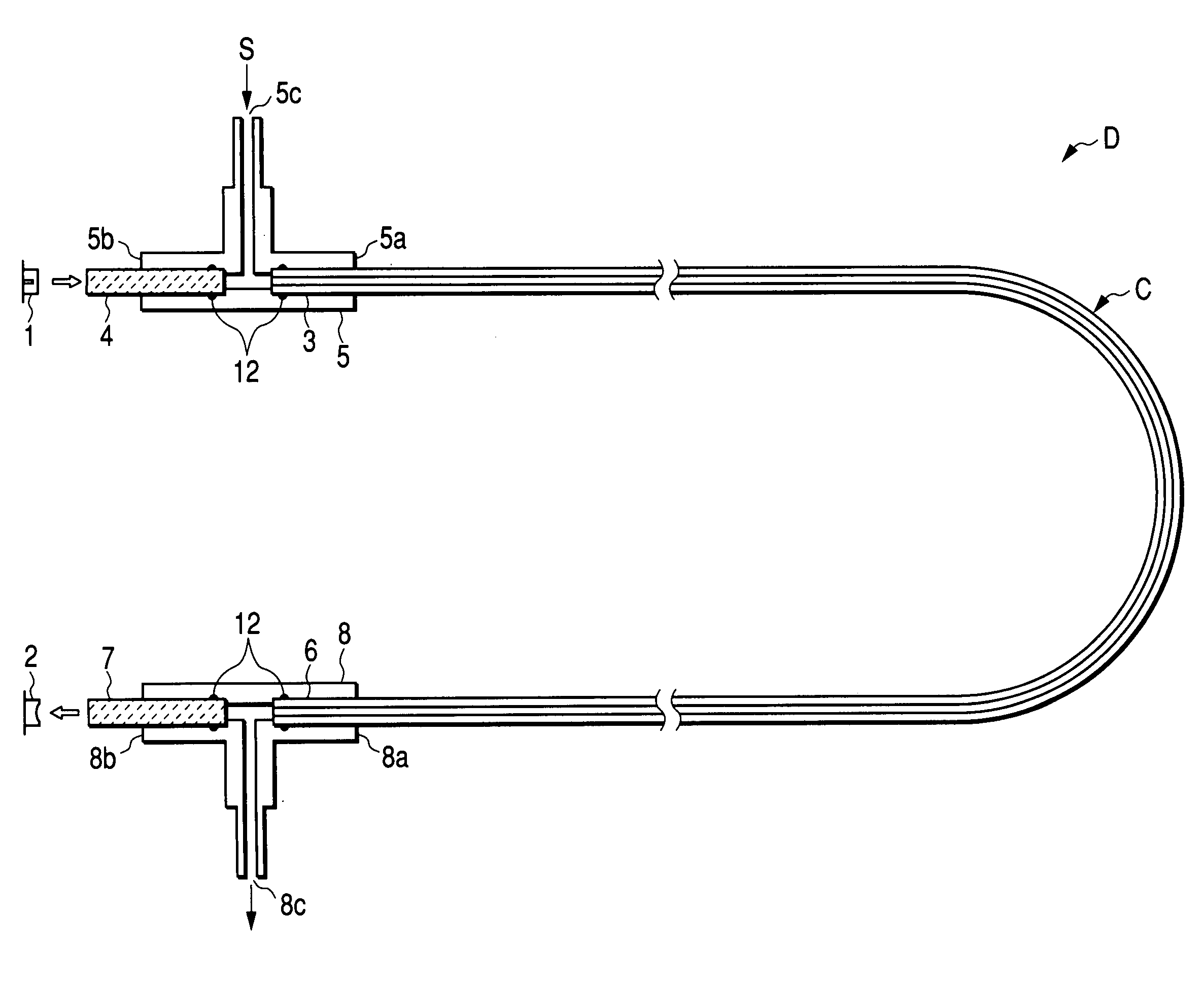
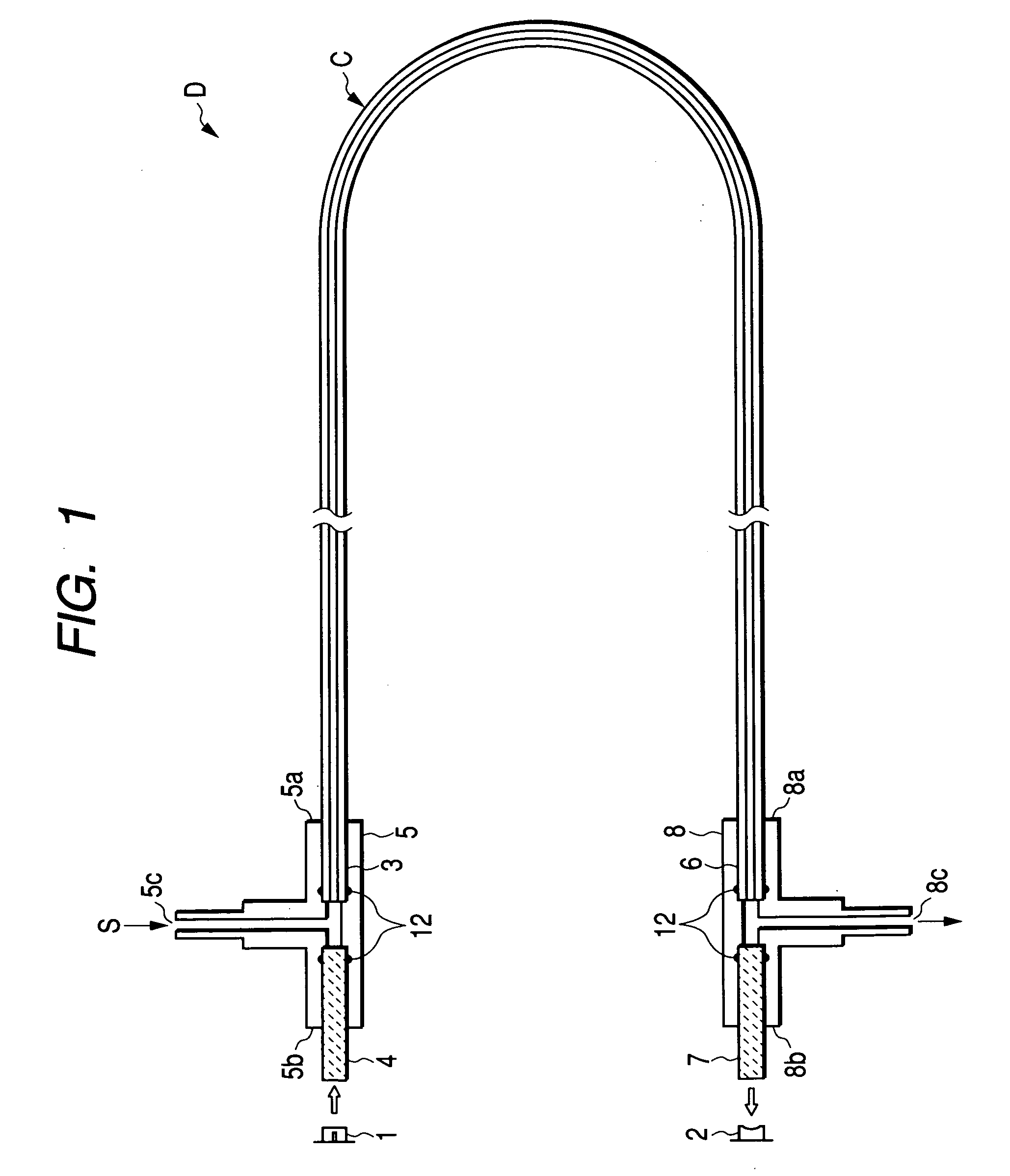
[0121] In the abovementioned fluid analyzer as shown in FIG. 1, as a concrete joint structure of a light incident portion and a light exit portion, a constitution shown in FIG. 11 is employed. That is, at joint portions of both ends of a resinous tube 151 constituting a cell C and a light intake window member 153 made of glass that introduces light from a light source 152 into the interior of the resinous tube 151 and a light takeout window member 155 made of glass that takes out the light past through the interior of the resinous tube 151 toward a detector 154, and at joint portions of both ends of the resinous tube 151 and a resinous intake tube 156 that introduces a subject liquid (hereinafter, containing one called a sample liquid) and a reference liquid into the cell C and a resinous takeout tube 157 that takes out the sample liquid and the reference liquid from the cell C, respectively, T-shaped connectors 158 and 159 are inserted, the respective constituents 151, 153 and 156 ...


PUM


Abstract

A ell for analyzing fluid and an analyzing apparatus using the cell which can improve the degree of freedom as to the arrangement of the cell, be disposed at a small space, obtain a sufficient optical length by a small amount of sample, does not require a large-sized light shielding mechanism nor an additional many constituent parts and can change the optical length easily. In a cell C for analyzing fluid configured in a manner that sample S flows therein and irradiation light passes through the sample S, the cell includes an inner tube in which the sample S passes, a protection tube formed on the outside of the inner tube to hold the shape of the inner tube, and a reflection layer formed between the inner tube and the protection tube to reflect the light passing within the inner tube. Further, on both ends of a fluid analyzing cell constituted of a light-transmitting resinous tube, a light incidence portion from a light source to an interior of the cell 1 and a light exit portion to a detector detecting light past through the interior of the cell are circularly curved with a shape of a cross section of a flow path maintaining same as that of a linear cell portion to make the flow path of the sample liquid S turn gradually to form a right angle.

Description

BACKGROUND OF THE INVENTION [0001] The present invention relates to a fluid analyzer that, like for instance a silica analyzer, by illuminating light to a subject liquid contained in a cell and detecting light intensity past through the cell, measures and analyzes the absorbance and light transmittance of the subject liquid. In detail, the invention relates to a fluid analyzer having a fluid analyzing cell made of a light-transmitting material and constituted so that the subject liquid flows inside thereof, a light source disposed at one end side of the cell so as to illuminate light toward an interior of the cell, and a detector that is disposed at the other end side of the cell and detects light past through the interior of the cell. [0002] In the cell for analyzing fluid which is configured in a manner that sample flows therein, an irradiation portion for irradiating light toward the sample is disposed at one end side of the cell, and a detector for detecting the light irradiated...

Claims


Application Information

Patent Timeline
IPC IPC(8): G01N21/05
CPCG01N21/0303G01N2021/0346G01N21/05
Inventor UCHIMURA, KOJITAJIRI, TOMOENAKATSUKASA, TADASHI
Owner HORIBA LTD
Why Eureka
Try Eureka