
Distance measuring apparatus and distance measuring method

Active Publication Date: 2013-12-17
KK TOPCON
View PDF13 Cites 0 Cited by
  • Summary
  • Abstract
  • Description
  • Claims
  • Application Information

AI Technical Summary

Benefits of technology

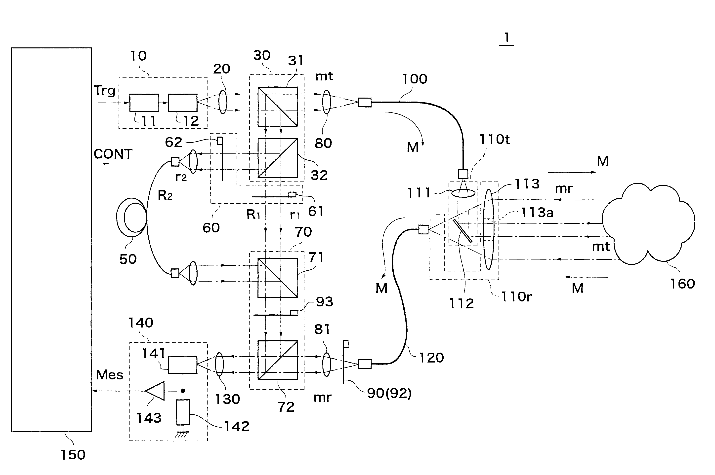
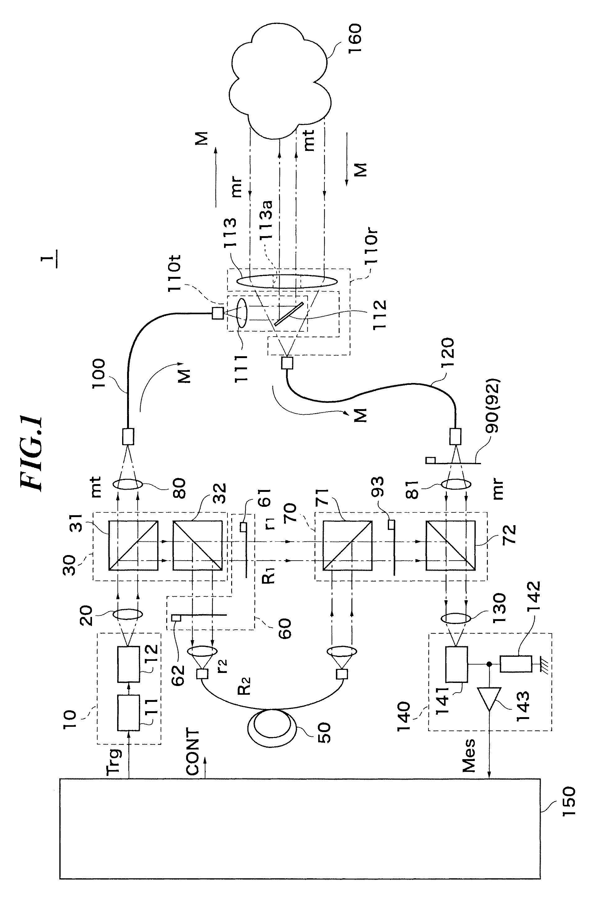
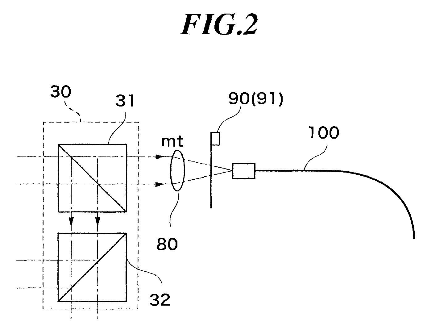
The present invention provides a distance measuring apparatus with high accuracy over a wide distance range from a short distance to a long distance. The apparatus has a referenced light path and a measurement light path, which can be independently controlled between a blocked state and a transmission allowed state. By adjusting the levels of the transmitted and received measurement lights, the apparatus can measure the object under collimated conditions close to the received measurement light for distance calculation, without requiring cancellation of the collimated state. The apparatus also compensates for variations in delay time and temperature variations to ensure accurate measurement. Additionally, the apparatus uses an optical fiber to reduce its size and can perform high-accuracy measurement even at long distances.

Problems solved by technology

However, it is difficult for this method to operate rapidly, which gives a significant factor that restricts shortening of the measurement time.
In the case where the distance between the object to be measured 160 and the distance measuring apparatus 100 is short, however, the reference light rc and the measurement light mc may overlap each other on the time axis, which may make it difficult to accurately detect the time lag between the reference light rc and the measurement light mc (see case 1 in FIG. 15B).
If the time of passage through the reference light path Rc is short, the induced noise may overlap the reference light rc on the time axis to cause a measurement error.
However, the propagation delay time of the optical fiber is varied depending on the temperature.
Such an error is not allowable for a precise distance measuring apparatus that aims at a measurement accuracy of about 1 mm.

Method used


Image

  • Distance measuring apparatus and distance measuring method
  • Distance measuring apparatus and distance measuring method
  • Distance measuring apparatus and distance measuring method

Examples


Embodiment Construction

[0059]The basic Japanese Patent Application No. 2008-330162 filed on Dec. 25, 2008 is hereby incorporated in its entirety by reference into the present application.

[0060]The present invention will become more fully understood from the detailed description given hereinbelow. The other applicable fields will become apparent with reference to the detailed description given hereinbelow. However, the detailed description and the specific embodiment are illustrated of desired embodiments of the present invention and are described only for the purpose of explanation. Various changes and modifications will be apparent to those ordinary skilled in the art on the basis of the detailed description.

[0061]The applicant has no intention to give to public any disclosed embodiments. Among the disclosed changes and modifications, those which may not literally fall within the scope of the present claims constitute, therefore, a part of the present invention in the sense of doctrine of equivalents.

[00...


PUM


Abstract

A distance measuring apparatus and method that enable high-precision and high-speed measurement by canceling variations of a delay circuit in the apparatus are provided. Pulsed light is branched into first and second reference light, and transmitted measurement light, and the difference in detection time among the first reference light along a first path with no optical variations, the second reference light along a second path with an optical delay, and received measurement light from an object to be measured is measured. The received measurement light and the first reference light are temporally separate, distance is calculated from the difference in detection time between the received measurement light and the first reference light. When the received measurement light and the first reference light are not temporally separate, distance is calculated from a difference in detection time between the first reference light and the second reference light and a difference in detection time between the received measurement light and the second reference light.

Description

TECHNICAL FIELD[0001]The present invention relates to a distance measuring apparatus and a distance measuring method in which the time from radiation of a light pulse to an object to be measured to return of reflected light is measured to measure the distance from the object to be measured. More specifically, the present invention relates to a distance measuring apparatus and a distance measuring method in which a distance measuring apparatus adopts a measurement scheme with a delay element included in a reference light path, the apparatus and the method enabling high-precision measurement by canceling the influence of temperature variations on delay time of the delay element or the like.BACKGROUND ART[0002]Hitherto, there has been a distance measuring apparatus that radiates pulsed light to an object to be measured and then detects the pulsed light reflected from the object to be measured to measure, using the road-trip propagation time of the pulsed light, the distance to the obje...

Claims


Application Information

Patent Timeline
IPC IPC(8): G01C3/08G01S17/34G01S17/10
CPCG01S7/497G01S17/325G01S17/10G01S17/34
Inventor OHISHI, MASAHIROTOKUDA, YOSHIKATSU
Owner KK TOPCON
Learn More