
Electric distribution box

Inactive Publication Date: 2006-11-16
YAZAKI CORP
View PDF8 Cites 9 Cited by
  • Summary
  • Abstract
  • Description
  • Claims
  • Application Information

AI Technical Summary

Benefits of technology

[0012] It is therefore an object of this invention to provide an electric distribution box which is provided with at least one pair of cassette blocks, and can be enhanced in degree of freedom of installation thereof.

Problems solved by technology

Therefore, the length of the combined (pair of) fuse blocks becomes long, so that a space in which the pair of fuse blocks can be located has tended to be limited.
Namely, the installation of the electric distribution box has tended to affect the arrangement of other equipments of the automobile, or the position in which the electric distribution box is installed has tended to be limited (Namely, the degree of freedom of installation of the electric distribution box has tended to be decreased.)

Method used


Image

  • Electric distribution box
  • Electric distribution box
  • Electric distribution box

Examples


Embodiment Construction

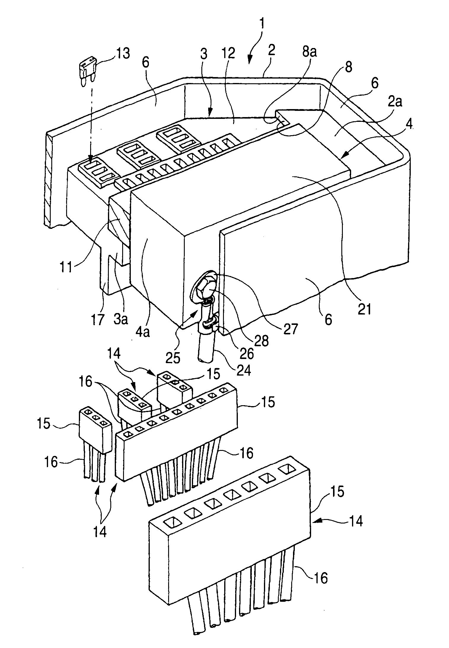
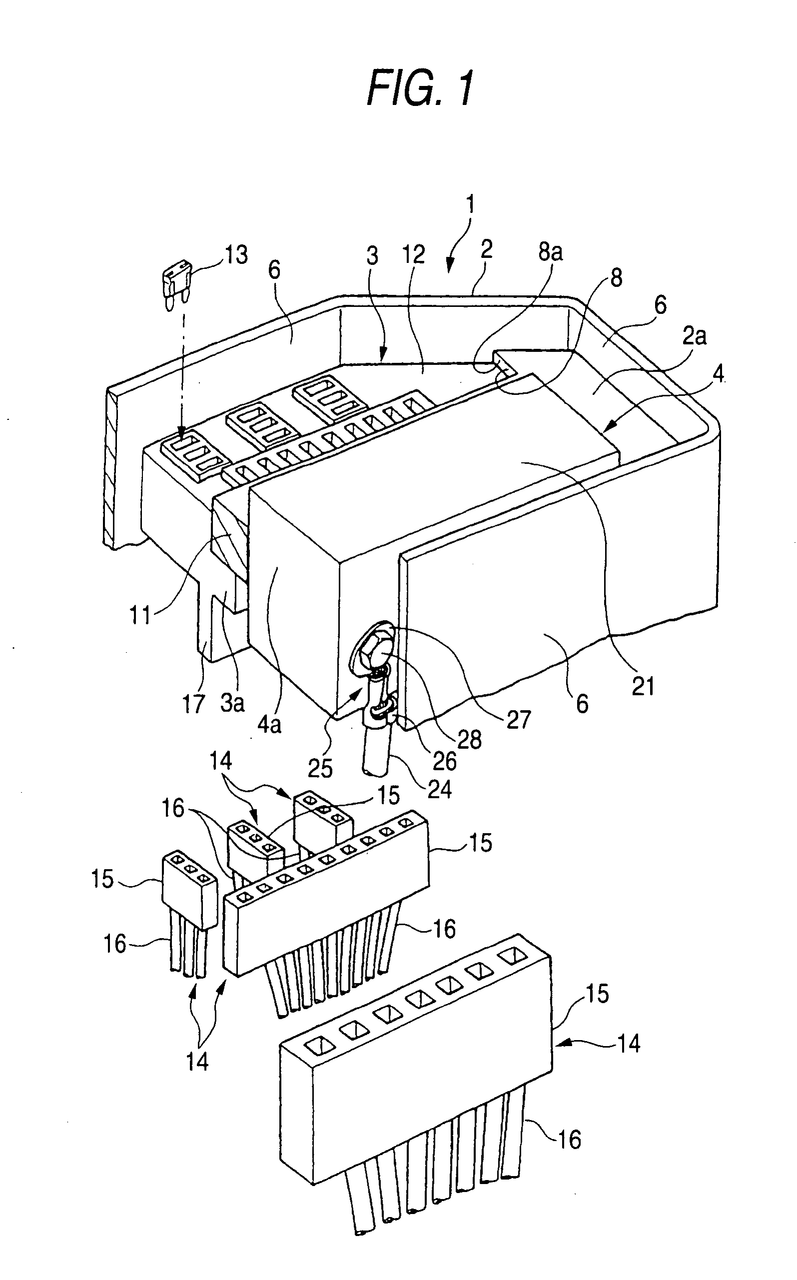
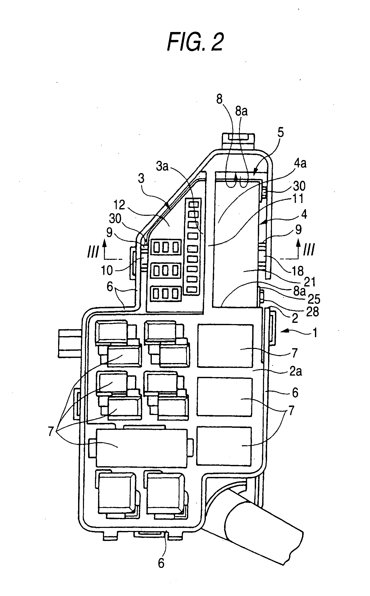
[0037] One preferred embodiment of an electric distribution box of the present invention will now be described with reference to FIGS. 1 to 7.

[0038] The electric distribution box 1 of this embodiment, shown in FIG. 1, is mounted on an automobile serving as a mobile body. As shown in FIGS. 1 to 4, the electric distribution box 1 comprises a box body 2, a fuse block 3 serving as a cassette block, a multi-fuse block 4 serving as a cassette block, wiring boards (not shown), a bus bar 5 (shown in FIGS. 2 and 4).

[0039] The box body 2 is made of an insulative synthetic resin, and is molded by a well known injection molding method. The box body 2 is formed into a generally tubular shape (box-shape) by a plurality of outer walls 6.

[0040] A plurality of electric parts such as relays 7 are mounted on an upper surface 2a (disposed at the upper side in FIG. 1) of the box body 2.

[0041] Connectors of wire harnesses (not shown), installed on the automobile, are fitted to a bottom surface (dispo...


PUM


Abstract

An electric distribution box includes a first cassette block that includes a flat face having a first long side and a second short side, and provided with a first electric parts, a second cassette block that includes a flat face having a second long side and a second short side, and provided with a second electric parts, and a bus bar that connects a terminal of the first electric parts to a terminal of the second electric parts. The first cassette block is arranged with the second cassette block so that the first long side of the first cassette block and the second long side of the second cassette block are disposed in parallel and opposed to each other. The bus bar is disposed along outer surfaces of the first and second cassette blocks.

Description

BACKGROUND OF THE INVENTION [0001] This invention relates to an electric distribution box for mounting on an automobile serving as a mobile body. [0002] Generally, various electronic equipments, including lamps such as headlamps and tail lamps and motors such as a starter motor and an air-conditioner motor, are mounted on an automobile serving as a mobile body. [0003] In order to supply electric power to the above various electronic equipments, a junction block, serving as a power distribution box, has been located at a suitable portion of the automobile. The junction block is formed by combining various electric circuit units of many fuses, relays, etc., together. [0004] The junction block includes fuses, relays, bus bars, etc., and therefore is often called a fuse block or a relay box, or generically called an electric distribution box. In the present specification, the fuse block, the relay box and the junction block will hereafter be generically called an electric distribution b...

Claims


Application Information

Patent Timeline
IPC IPC(8): H05K1/00
CPCH01R2201/26H01R13/518
Inventor EGAWA, MASATOSHINAKAYAMA, TAKUYASEKINE, YUMISUGIURA, MAKI
Owner YAZAKI CORP
Learn More