Modular fore-end rail assembly for firearms

a module and foreend rail technology, applied in the direction of weapons, butts, sighting devices, etc., can solve the problems of prior art interface rails, multiple sighting devices of military personnel, and need support both on the receiver end and the end of the barrel, so as to prevent any load from entering the barrel, facilitate the removal of the lower portion, and prevent any load from being transferred.

Inactive Publication Date: 2006-11-23
TROY STEPHEN P JR
View PDF27 Cites 76 Cited by
  • Summary
  • Abstract
  • Description
  • Claims
  • Application Information

AI Technical Summary

Benefits of technology

This patented innovation describes a new design for attaching a main rod (or gun) to a fire arm's receivers during use or disassembly. By combining these components together, there are fewer parts needed compared to traditional methods like welded connections between them. These improvements make it easier to remove and replace existing equipment when necessary.

Problems solved by technology

The technical problem addressed in this patent is the need for a modular fore-end rail assembly that can be used to mount accessories to a firearm without adding excess weight or stress to the barrel, while also providing a convenient way to access the barrel for maintenance or replacement without having to remove the entire assembly from the firearm. Additionally, there is a need for a modular fore-end rail assembly that can be easily removed and replaced without modifying the existing barrel nut.

Method used


Image

  • Modular fore-end rail assembly for firearms
  • Modular fore-end rail assembly for firearms
  • Modular fore-end rail assembly for firearms

Examples


Embodiment Construction

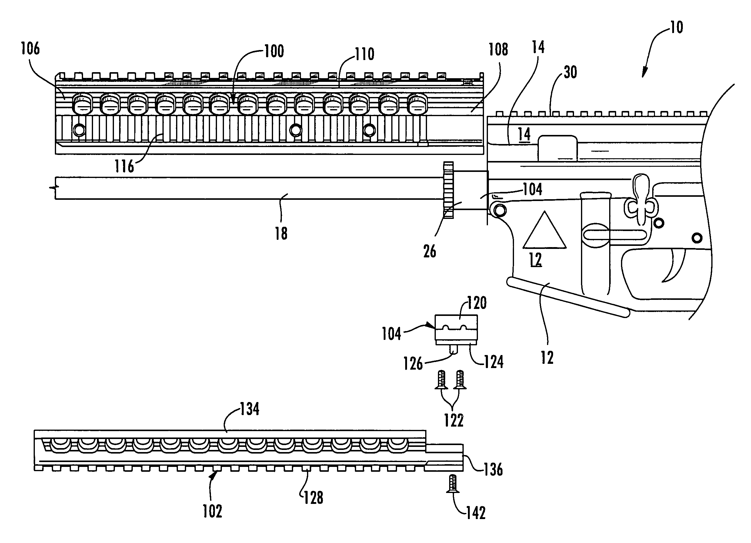
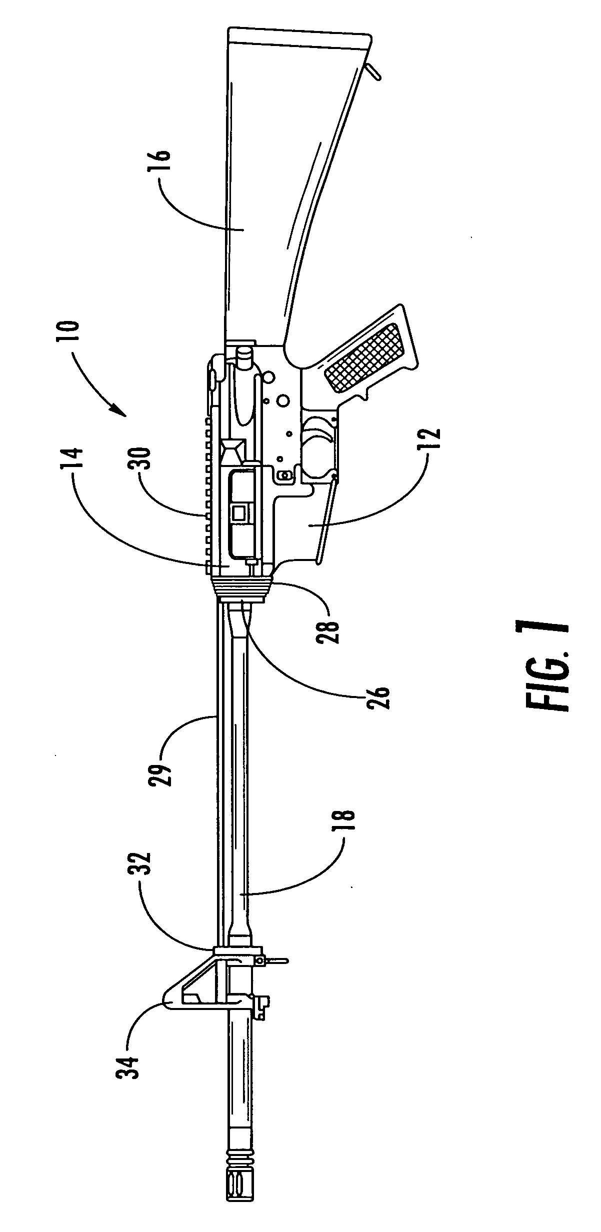
[0022] Now referring to the drawings, the modular fore-end rail assembly of the present invention is shown and generally illustrated in FIGS. 3-7. As can be seen the modular fore-end rail assembly of the present invention generally includes an upper hand guard 100, a lower hand guard 102 and a clamping assembly 104.

[0023] The upper hand guard assembly 100 is the structural element that supports the entire fore-end rail assembly and serves to transfer the loads or additional weight induced by any attachments into the upper receiver 14 of the firearm 10. The upper hand guard 100 is formed generally as the upper half of a tubular enclosure that is configured to encircle the barrel 18 of the firearm 10 when the fore-end rail assembly is installed on the firearm 10 in a mounted position. The upper hand guard 100 has a forward end 106 and a rearward end 108 and a standard dovetail rail 110 extending longitudinally between the forward end 106 and the rearward end 108. The upper hand guard...


PUM


Abstract

A modular fore-end rail assembly for mounting onto a firearm includes an upper hand guard, a lower hand guard and a clamping member that combines with the rear portion of the upper hand guard to encircle and clamp onto the barrel nut thereby supporting the entire assembly from the front of the upper receiver and preventing any transfer of load into the barrel. The lower portion of the hand guard is slidably received into channels formed in the upper hand guard and is retained in its installed position by a spring biased detent located in the clamping member. The lower hand guard is removable by simply depressing the detent and sliding the lower hand guard forward. By providing for the easy removal of the lower hand guard, other auxiliary devices may be mounted to the upper hand guard.

Description


Claims


Application Information

Patent Timeline
Owner TROY STEPHEN P JR
Why Eureka
Try Eureka