Hook connector with plastic fire relief

a technology of fire relief and connectors, which is applied in the direction of ceilings, walls, flooring, etc., can solve the problems of sagging or drooping of the suspended ceiling, affecting the visual and structural appearance of the ceiling, and affecting the stability of the suspended ceiling. , to achieve the effect of preventing sagging or drooping of the cross beam

Active Publication Date: 2006-11-23
WORTHINGTON ARMSTRONG VENTURE
View PDF24 Cites 6 Cited by
  • Summary
  • Abstract
  • Description
  • Claims
  • Application Information

AI Technical Summary

Benefits of technology

[0014] The present invention involves a connector on the end of a cross beam, in a grid in a suspended ceiling. The connector, which engages a slot in a main beam, is capable of permitting, in a fire, the cross beam to expand longitudinally and stay aligned to continue to support a panel, while keeping the cross beams from sagging or drooping.
[0016] In the present improvement, the connector is formed with an inner metallic core having a certain configuration, and a plastic encasement of the configured metallic core, having a configuration with added abutments to the metallic core. These abutments formed by the plastic encasement help position the connector within the slot, and particularly, bar further entry of the connector into the slot, under normal conditions.
[0018] The remaining inner metallic core of the connector, which remains structurally sound during a fire, continues to support the connector within the slot, so that the cross beam, in its expanded state, is still supported by the main beam. The metallic core also has ridges that are capable of successively engaging the main beam slot to prevent pullback of the connector during a fire, so that the ceiling does not sag or droop.

Problems solved by technology

Additionally, during a fire, the suspended ceiling 10, including the beams and panels, tends to weaken from the heat of the fire, and sag or droop from the normally flat plane of the ceiling.
Once the fire subsides, the ceiling 10 is generally replaced, since even though the ceiling desirably survives the fire relatively intact to provide such heat shield to the structural ceiling, visually and structurally the ceiling is generally impaired.

Method used


Image

  • Hook connector with plastic fire relief
  • Hook connector with plastic fire relief
  • Hook connector with plastic fire relief

Examples


Embodiment Construction

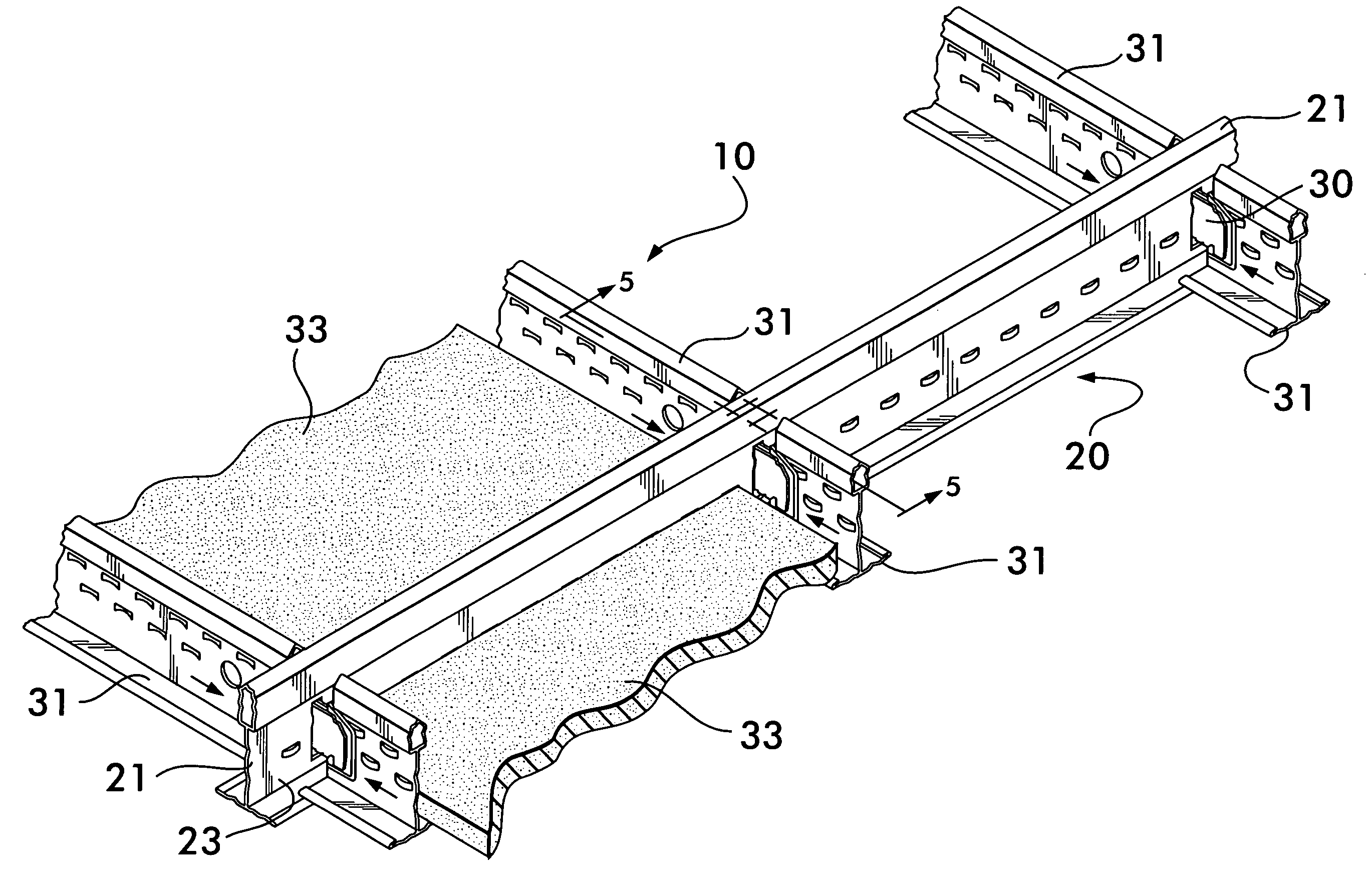
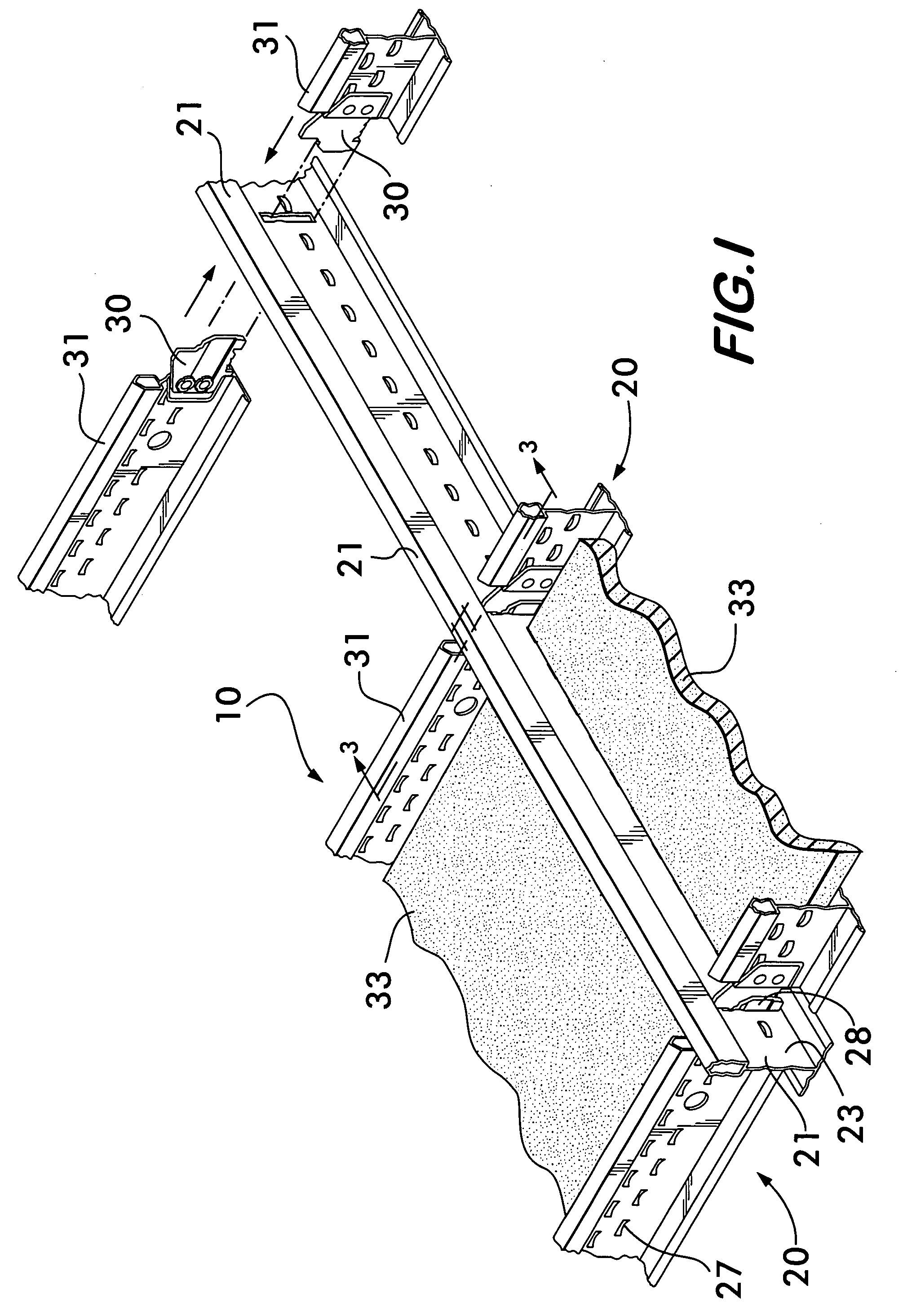
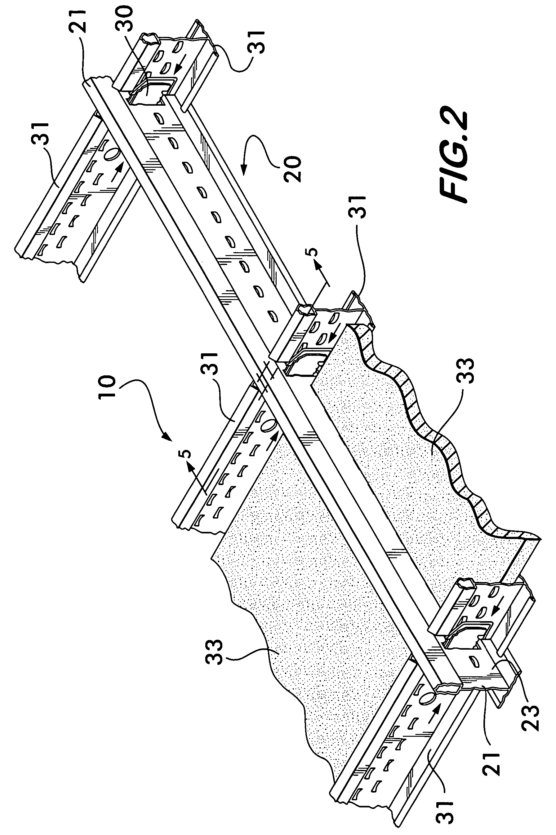
[0033] In FIG. 1, there is shown a grid 20 in a suspended ceiling 10, partially assembled, using the present invention. Main beam 21 is of an inverted T cross section and has a bulb 22, a web 23, and opposing flanges 25 and 26. The web 23 has stitches 27 that strengthen the beam 21. Such beam construction is well known and is of the type shown, for instance, in U.S. Pat. No. 6,138,416, incorporated herein by reference. The stitches 27 are of a type shown, for instance, in U.S. Pat. No. 5,979,055, incorporated herein by reference.

[0034] The suspended ceiling 10 is formed of a metallic grid 20 that supports ceiling panels 33 formed of a fire resistant substance, as well known in the art. Grid 20 has, in the main beams 21, slots 28 spaced longitudinally along webs 23 that receive connectors 30 on the end of cross beams 31.

[0035] The connectors 30 on cross beams 31 are secured on the ends of the cross beams 31 by riveting or peening, as for instance seen in the '343 patent.

[0036] Opp...


PUM


Abstract

A connector for a cross beam that hooks into a slot in a main beam in the grid of a suspended ceiling. The connector has a plastic encasement that forms abutments about a metallic core. The abutments position the connector within the slot, and prevent further entry of the connector into the slot, under normal conditions. The plastic abutments melt away during a fire, so that the beam can expand longitudinally to relieve stresses in the beam, without the beam buckling. Ridges on the bottom of the metallic core prevent pullback of the connector from the slot, during a fire, to prevent the ceiling from sagging or drooping.

Description

BACKGROUND OF THE INVENTION [0001] (1) Field of the Invention [0002] This invention relates to a metallic grid structure for a suspended ceiling, and more particularly to a connector in such structure that aids in keeping the ceiling intact, and without sagging from its own weight, during a fire. [0003] (2) The Prior Art [0004] A typical prior art suspended ceiling 10 is shown in FIG. 1 of the present drawings, wherein, in a grid 20, main beams 21 extend parallel to one another, at, for instance, 4′ intervals. Cross beams 31 in the grid 20 span the distance between the main beams 21 and interlock with the main beams 21 through slots 28 in the main beams 21. [0005] In the grid 20, main beams 21 are connected end to end in a variety of ways, including the one shown in U.S. Pat. No. 6,523,313, incorporated herein by reference. Cross beams generally are connected to the main beams through slots in the main beams 21, as for instance, by a hook in a connector, as shown, for instance, in U...

Claims


Application Information

Patent Timeline
Patent Type & Authority Applications(United States)
IPC IPC(8): E04B9/00
CPCE04B9/068E04B9/122E04B9/08Y10S52/05
Inventor PLATT, WILLIAM J.LIN, YU
Owner WORTHINGTON ARMSTRONG VENTURE
Why Eureka
Try Eureka