
Vascular anchoring introducer sheath

An introducer, sheath technology, used in catheters, trocars, balloon catheters, etc.

Pending Publication Date: 2020-02-14
MUFFIN +1
View PDF16 Cites 0 Cited by
  • Summary
  • Abstract
  • Description
  • Claims
  • Application Information

AI Technical Summary

Problems solved by technology

Such devices allow access, but typically lack any structure to retain the device relative to the tissue through which it is deployed, as such anchoring is not required or desired

Method used


Image

  • Vascular anchoring introducer sheath
  • Vascular anchoring introducer sheath
  • Vascular anchoring introducer sheath

Examples


Embodiment Construction

[0020] While the present disclosure may be embodied in many different forms, to promote an understanding of the principles of the disclosure, reference will now be made to the embodiments illustrated in the drawings, and specific language will be used to describe the same. It should be understood, however, that no limitation of the scope of the present disclosure is thereby intended. Any alterations and further modifications to the described embodiments and any further applications of the principles of the disclosure described herein are contemplated as would normally occur to one skilled in the art to which the disclosure pertains.

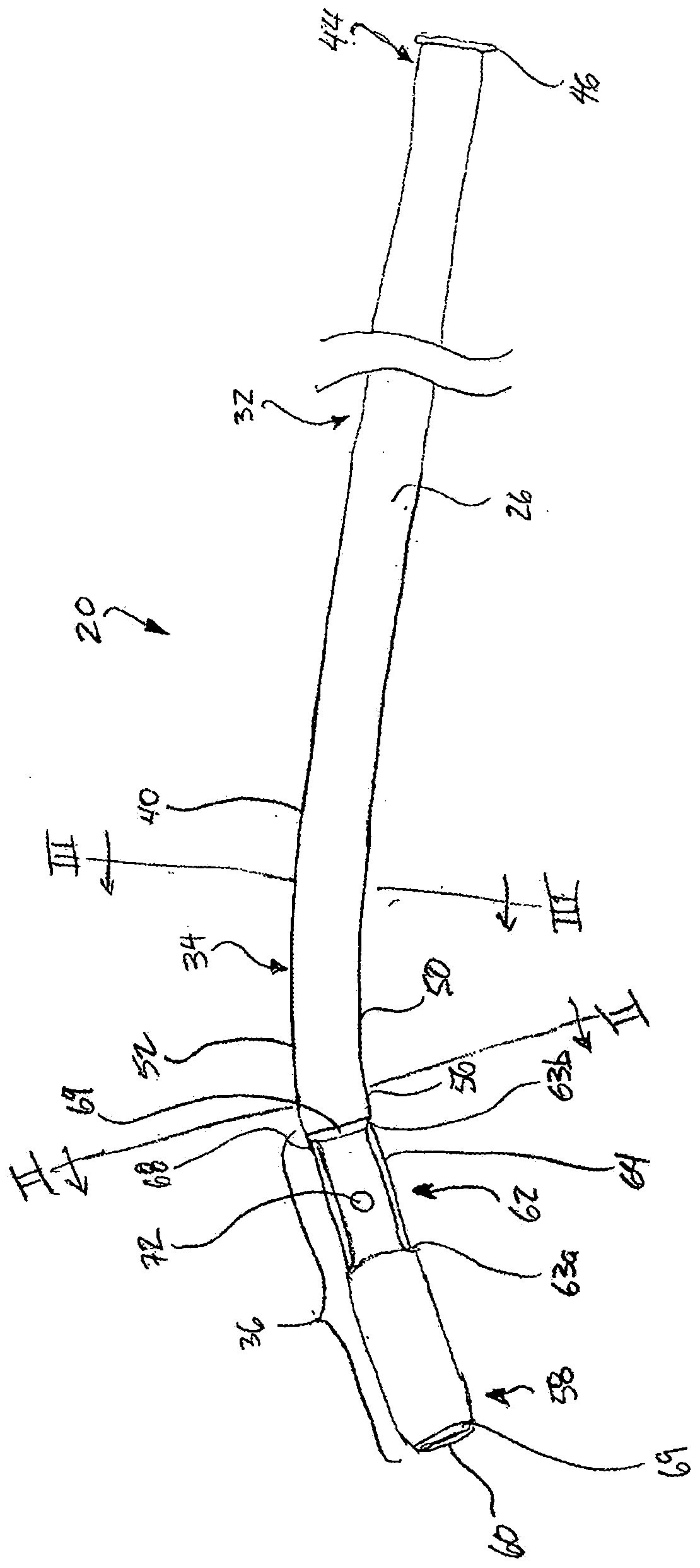
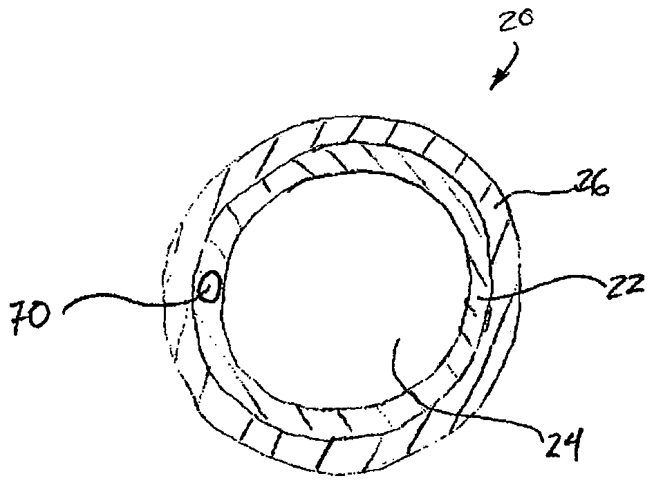
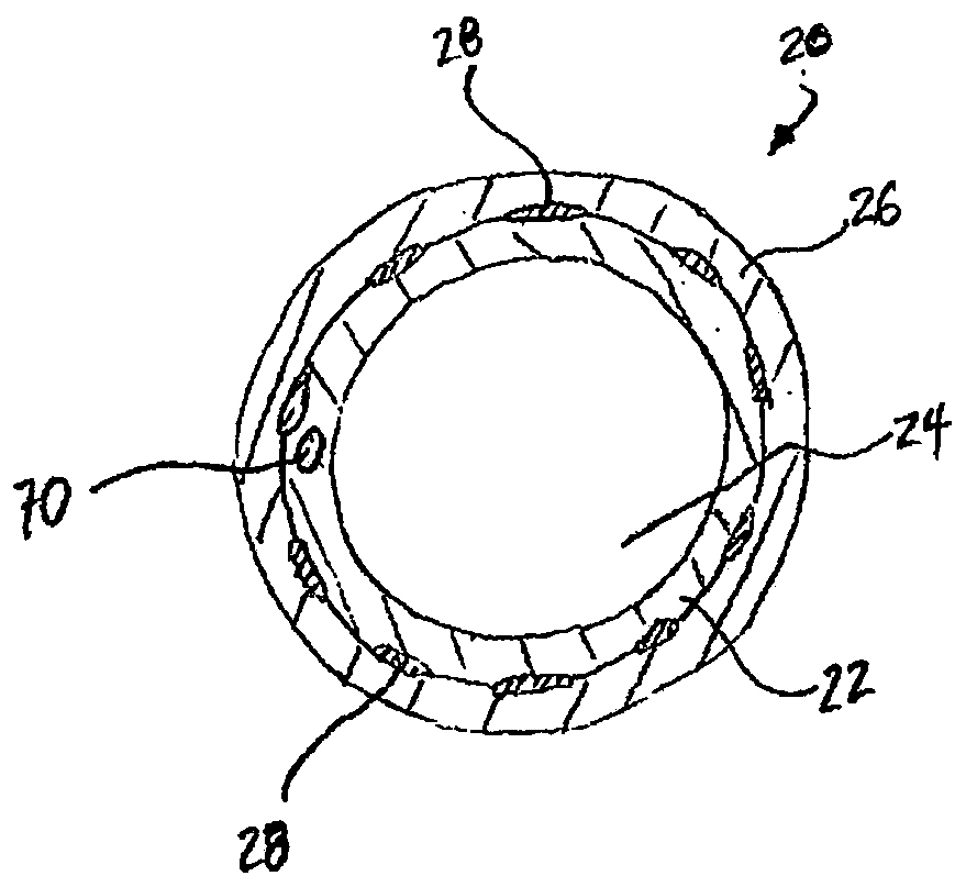
[0021] Referring now to the drawings generally, there is shown an embodiment of an introducer sheath 20 adapted for use within the body to allow other devices, such as catheters, diagnostic devices, or therapeutic devices, to be advanced through the sheath 20 to a desired location within the body. . For example, the sheath 20 is preferably capab...


PUM


Abstract

Provided are apparatus and methods for maintaining access to a location in the body while reducing or eliminating the potential for pulling an access device (e.g. a catheter) back through an opening.An introducer sheath (20) includes a distal indented portion (62) and a balloon (64), so that once placed in a desired location through tissue, the balloon can be inflated to anchor the sheath againstretraction. In particular examples, structure and methods for accessing the pericardial cavity via the right atrial appendage are shown.

Description

technical field [0001] The present disclosure relates to devices for secure anchoring relative to tissue, allowing other devices to be introduced through the device into a desired treatment site. In particular, the present invention relates to an introducer that can be inserted and anchored relative to tissue, such as the right atrial appendage. This application claims priority to US Provisional Application Serial No. 62 / 412646, filed October 25, 2016, which is hereby incorporated by reference in its entirety. Background technique [0002] In many applications, the vascular introducer sheath is threaded through tissue and inadvertent pulling back is undesirable. For example, a common approach to the left atrium of the heart is via the venous system into the right atrium and puncturing the interatrial septum to the left atrium. Once through the septum, if the introducer is inadvertently pulled through the septum and back into the right atrium, the septum must be repeatedly ...

Claims


Application Information

Patent Timeline
Patent Type & Authority Applications(China)
IPC IPC(8): A61M25/10A61M25/00A61B17/00A61B17/34
CPCA61M25/0041A61M25/0045A61M25/0054A61M25/0108A61M25/0662A61M25/10A61B2017/00247A61B2017/3486A61M2025/0047A61M2025/1079A61M2025/1093A61M25/0052A61B90/39A61B2090/3925A61B2090/3966A61B17/0218A61B2017/00557A61B2017/00845A61B2017/00955A61B2017/0225A61B2017/0237
Inventor S·D·吉塔德G·J·哈迪小约翰·C·西格蒙J·T·纽柯克W·J·哈韦尔N·E·费尔诺特R·J·莱德曼T·罗杰斯K·拉特纳亚卡
Owner MUFFIN
Learn More