Firearm apparatus and method

a technology of firearms and projectiles, which is applied in the field of firing projectiles, can solve the problems of improving the core functional features of firearms, poor shooting accuracy of today's firearms, and reducing the accuracy of shooting, so as to minimize the angle of departure, minimize the displacement of firearms during firing, and achieve high shooting accuracy

Inactive Publication Date: 2006-11-23
ROZHKOV LEONID +1
View PDF12 Cites 16 Cited by
  • Summary
  • Abstract
  • Description
  • Claims
  • Application Information

AI Technical Summary

Benefits of technology

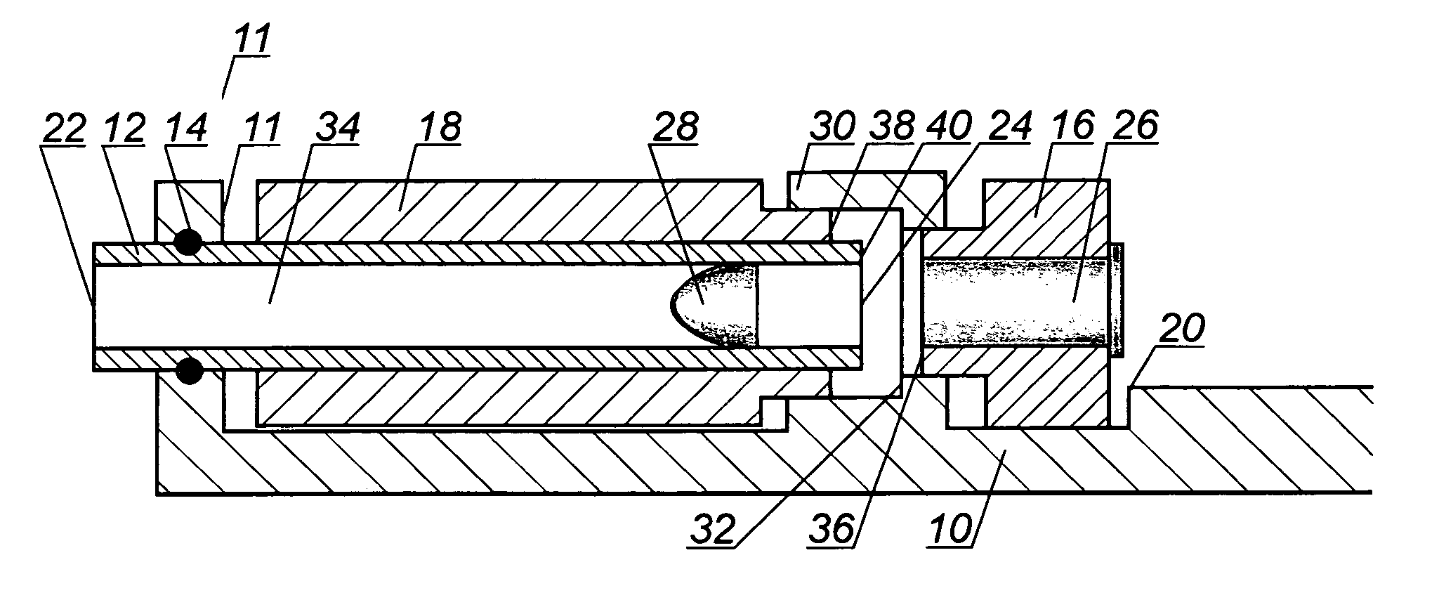
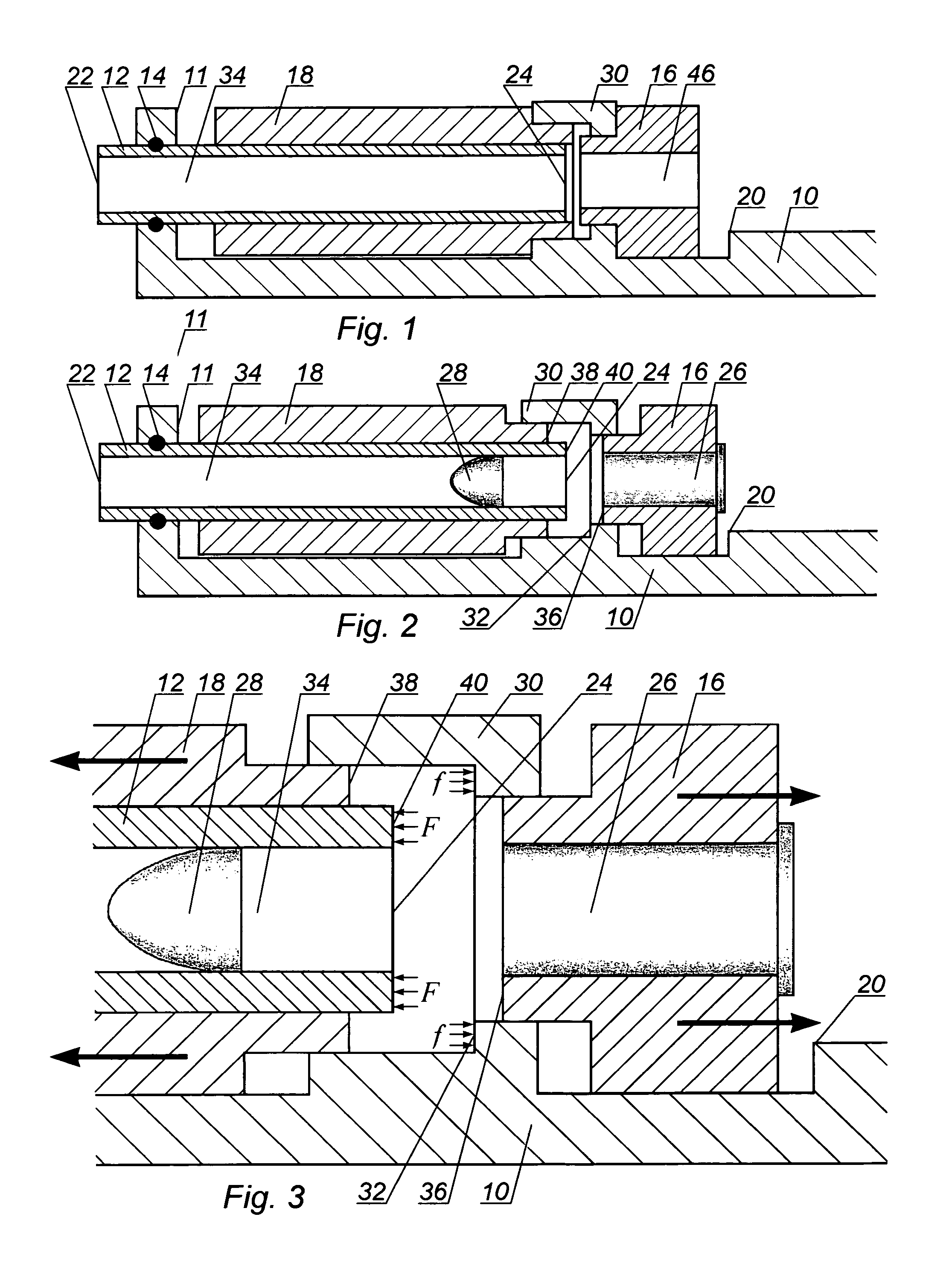
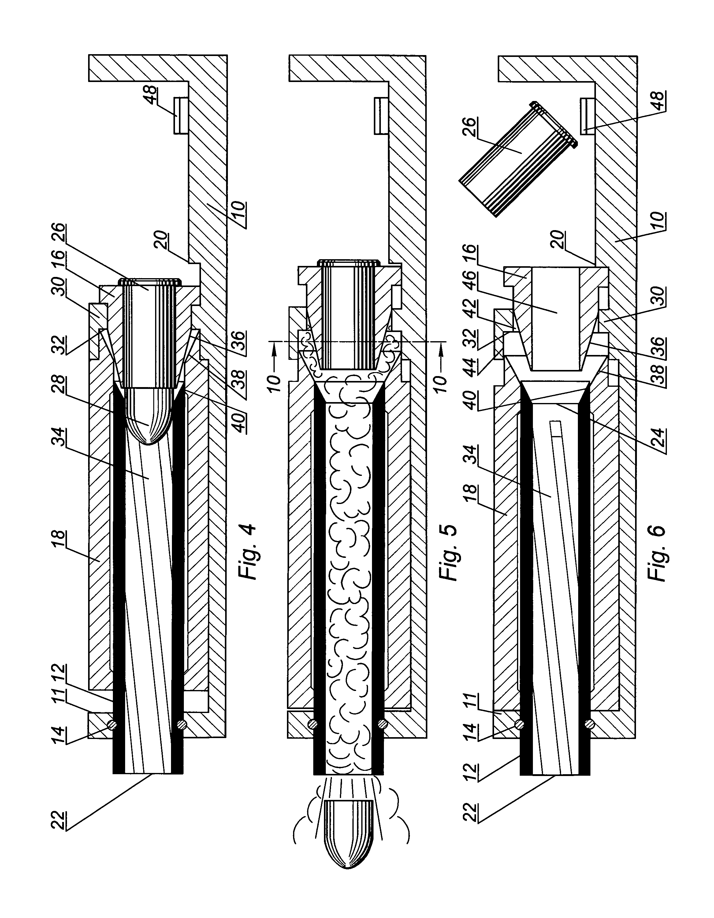
[0010] The present invention addresses the problem of minimizing the angle of departure in firearms and offers solutions applicable to most small and large barreled arms. Most embodiments shown feature a barrel immovably fixed in the firearm's frame, a movable chamber or cartridge container, and a stand formed as a portion of the frame and having a pressure surface. Stabilization of the firearm during firing is achieved by making the net forces generated by gas pressure apply in opposite directions and be substantially equal in magnitude, thus minimizing any displacement of the firearm during firing and achieving ve

Problems solved by technology

Major small arms developers' product lines are based on such generic-design firearms manufactured only with some cosmetic modifications or minor structural changes most of which do not make any significant improvements to the firearm's core functional features.
As a result, today's firearms have inherited such functional weaknesses as poor accuracy of shooting due to large projectile dispersion (often as a result of a trade-off for reliability), significant recoil, especially when used with high-energy ammunition, and complicated design.
This produces a significant angle between the axis line of the barrel bore immediately prior to firing and at the moment the projectile leaves the muzzle, referred to as the angle of departure, which is a major contributing factor to projectile dispersion and hence inaccuracy of shooting.
Si

Method used


Image

  • Firearm apparatus and method
  • Firearm apparatus and method
  • Firearm apparatus and method

Examples


case embodiment

FIG. 12—First Special-Case Embodiment

[0074] A first special-case embodiment shown in FIG. 12 is very similar in design and operation to the preferred embodiment described above and shown in FIGS. 1 through 11, therefore only aspects specific to this embodiment will be discussed here in detail.

[0075] The firearm schematically shown in FIG. 12 features parts that partially form the expandable chamber with surfaces slanted at the same angle. In other words, cartridge container working surface 36, countermass back surface 38, and breech end surface 40 have the slanted surfaces defining the same angle with respect to the axis line of barrel bore 34. This structural feature results in the following operational effect: when gas from the deflagrating propellant fills the expandable chamber during firing, all surfaces exposed to the gas are acted upon by gas pressure of substantially the same magnitude. Unlike the design of the expandable chamber shown in FIG. 11, the expandable chamber in ...


PUM


Abstract

A firearm apparatus and a method of firing ammunition therefrom, where the method utilizes a barrel (12) having a breech end surface (40) and immovably affixed to frame (10), a stand pressure surface (32), and a cartridge container (16) with a cartridge case (26) therein and countermass main body (18) movable in opposite directions. Gas from a deflagrating propellant moves the movable members and applies directionally opposite forces upon the breech end surface (40) and the stand pressure surface (32), which results in the force cancellation and ensures that the barrel (12) remains stable during firing. This solves the problem of the angle of departure and contributes to a high accuracy of shooting.

Description

CROSS-REFERENCE TO RELATED APPLICATIONS [0001] This application claims the benefit of the filing of U.S. Provisional Patent Application Ser. No. 60 / 677,382, filed by these inventors on May 3, 2005, and the specification thereof is incorporated herein by reference. This application is related to pending U.S. patent application Ser. No. 11 / 001,450, filed Nov. 30, 2004, the disclosure of which also is incorporated herein.BACKGROUND OF THE INVENTION [0002] 1. Field of the Invention (Technical Field) [0003] The present invention relates generally to cannons and firearms, more particularly to a method of firing projectiles there from, and an apparatus that realizes the method. [0004] 2. Background Art [0005] Nearly all firearms used today are engineered according to the basic design solutions developed decades ago. Major small arms developers' product lines are based on such generic-design firearms manufactured only with some cosmetic modifications or minor structural changes most of whic...

Claims


Application Information

Patent Timeline
IPC IPC(8): F41A3/54
CPCF41A3/56F41A3/68F41A5/12F41A21/12F41A19/14F41A19/43F41A5/16
Inventor ROZHKOV, LEONIDROZHKOV, IGOR
Owner ROZHKOV LEONID
Why Eureka
Try Eureka