Method of preventing interference between radars and radar system having interference preventing function

a radar system and interference prevention technology, applied in the field of preventing interference between radars and to radar systems having a function, can solve the problems of complex system and high cost, difficult to apply such a countermeasure to the inference between two radars mounted on different vehicles, and achieve the effect of preventing interference, preventing interference, and preventing interference between two radars

Active Publication Date: 2006-11-23
DENSO CORP
View PDF7 Cites 52 Cited by
  • Summary
  • Abstract
  • Description
  • Claims
  • Application Information

AI Technical Summary

Benefits of technology

The present invention provides a method and system for preventing interference between radars. This is achieved by setting a cycle period and transmission time for each radar to ensure that radar waves do not interfere with each other. This formula is applicable to radar systems mounted on automotive vehicles for detecting objects in front or behind the vehicle. The invention prevents interference without using additional devices and ensures high detection accuracy.

Problems solved by technology

Further, when a pair of radars Ra and Rb each detecting obstacles located in neighboring areas, as shown in FIG. 5B, radar waves transmitted by the radar Rb may be received by the radar Ra, causing interference between radars Ra and Rb.
This makes the system complex and expensive.
However, it is difficult to apply such a counter measure to the inference between two radars mounted on different vehicles, as shown in FIG. 5A.
Even when the cycle periods of both radars are different from each other, as shown in FIG. 6B, the interference may occur continuously more than two times. When the interference occurs continuously more than two times, detecting accuracy of the radar system is greatly damaged.

Method used


Image

  • Method of preventing interference between radars and radar system having interference preventing function
  • Method of preventing interference between radars and radar system having interference preventing function
  • Method of preventing interference between radars and radar system having interference preventing function

Examples


Embodiment Construction

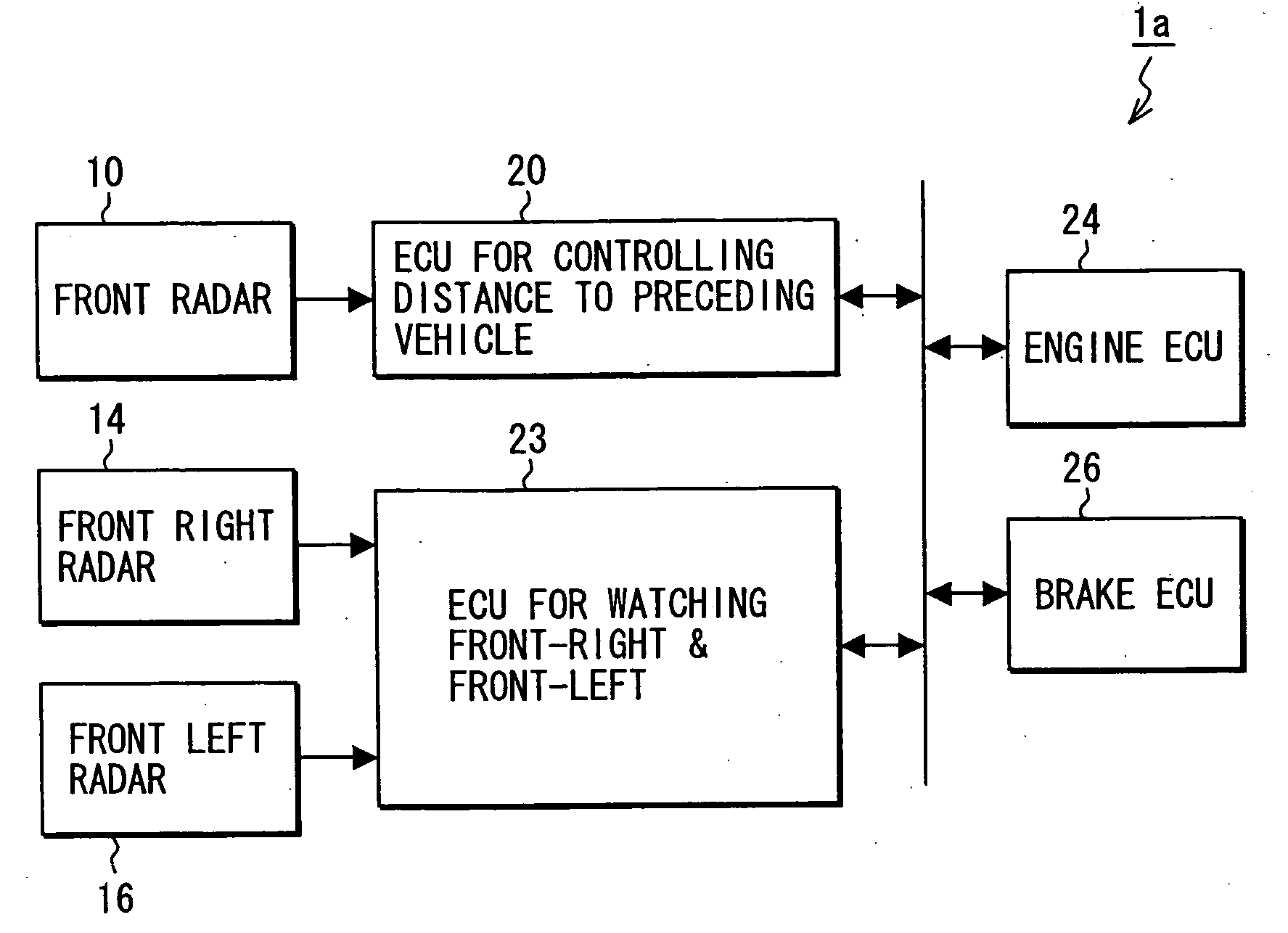
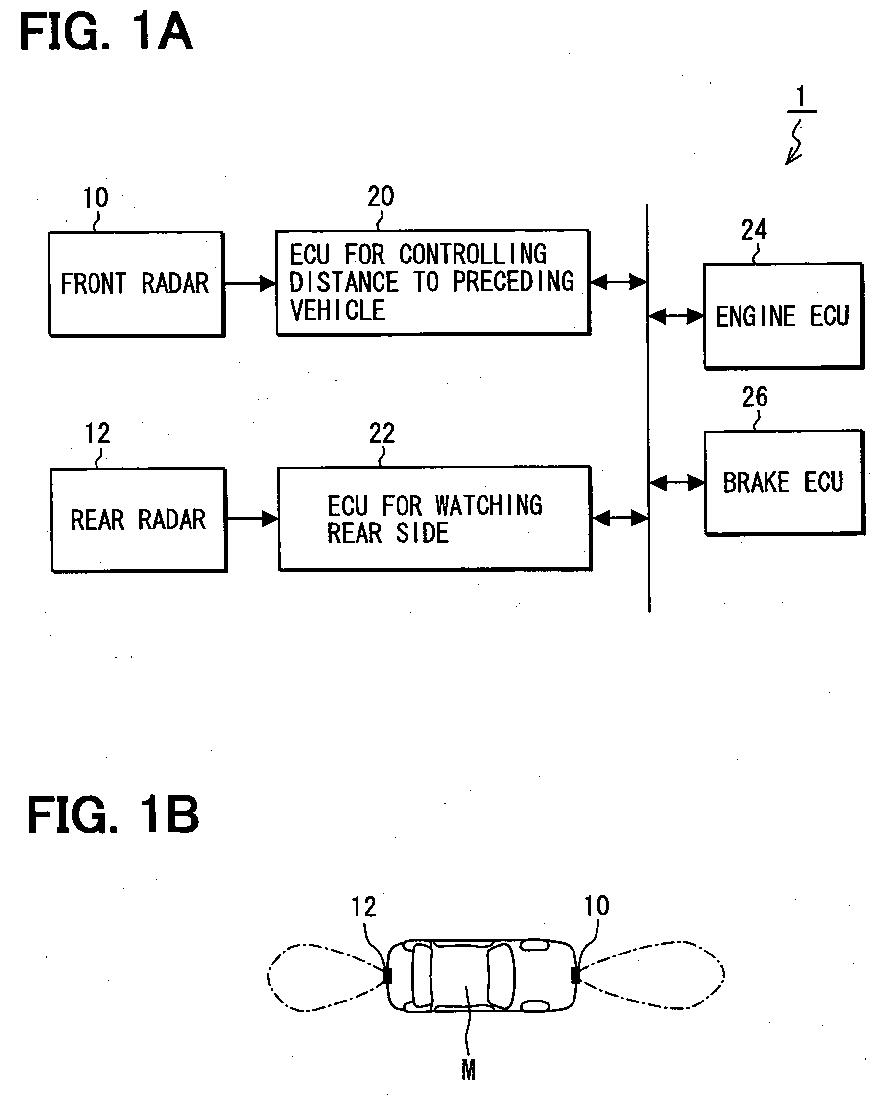
[0024] A first embodiment of the present invention will be described with reference to FIGS. 1A, 1B and 2. A block diagram of a radar system 1 mounted on an automotive vehicle is shown in FIG. 1A. A front radar 10 for detecting a front target such as a preceding vehicle or an object and a rear radar 12 for detecting a rear target such as a following vehicle or an object located behind a vehicle M are mounted on the vehicle M, as shown in FIG. 1B.

[0025] The radar system 1 includes the front radar 10, the rear radar 12, an electronic control unit (ECU) 20 for controlling a distance between the vehicle M and a preceding vehicle, an ECU 22 for watching rear side of the vehicle M, an engine ECU 24, a brake ECU 26. These components of the radar system 1 are interconnected through a local area network (LAN) communication bus. Each ECU (20, 22, 24, 26) is a known microcomputer including a bus controller for performing communication through the LAN communication bus. Data communication amon...


PUM


Abstract

A radar system mounted on a vehicle includes a first radar and a second radar, each having a transmitter-receiver and a signal processor. The transmitter-receiver transmits radar waves to detect objects such as another vehicle or other obstacles. An operating cycle period T1, T2 and a transmission time X1, X2 during which the radar waves are transmitted are set in both radars to satisfy the formula: K·T2+X2+X1≦T1≦(K+1)·T2−X2−X1 under a condition that T1>T2, where K is a positive integer. By setting both radars in this manner, interference between two radars is avoided without using additional devices in the radar system, and a high detection accuracy is realized.

Description

CROSS-REFERENCE TO RELATED APPLICATION [0001] This application is based upon and claims benefit of priority of Japanese Patent Application No. 2005-148485 filed on May 20, 2005, the content of which is incorporated herein by reference. BACKGROUND OF THE INVENTION [0002] 1. Field of the Invention [0003] The present invention relates to a method for preventing interference between radars and to a radar system having a function of preventing interference between radars. [0004] 2. Description of Related Art [0005] A radar system for detecting a target (such as a preceding vehicle or an obstacle) by transmitting radar waves and receiving waves reflected by the target has been known hitherto. If plural radars are mounted on a vehicle, interference between radars has to be prevented to secure detecting accuracy of the radars. [0006] When a pair of radars are mounted on a preceding vehicle M1 and a following vehicle M2, as shown in FIG. 5A, there is a possibility that interference occurs be...

Claims


Application Information

Patent Timeline
Patent Type & Authority Applications(United States)
IPC IPC(8): G01S13/93G01S13/931
CPCG01S7/36G01S13/931G01S2013/9325G01S2013/9378G01S2013/935G01S2013/9353G01S2013/9375G01S2013/9346G01S2013/9319G01S2013/93185G01S2013/93272G01S2013/93271G01S2013/932G01S7/0235
Inventor WATANABE, YUUNATSUME, KAZUMA
Owner DENSO CORP
Why Eureka
Try Eureka