
Method of and system for correcting image data, and its computer program

Inactive Publication Date: 2006-11-23
FUJIFILM CORP +1
View PDF19 Cites 4 Cited by
  • Summary
  • Abstract
  • Description
  • Claims
  • Application Information

AI Technical Summary

Benefits of technology

[0022] giving a larger correction value to the image data value output from a photo-sensor in the object line sensor nearer to an end of the reference line sensor facing the object line sensor so that the image data values output from photo-sensors in the object line sensor near to the end of the reference line sensor is connected to the image data value output from photo-sensors in the reference line sensor near to the end of the object line sensor facing the reference line sensor.
[0063] In accordance with the first method of correcting image data of the present invention, since the correction value of the image data value output from a photo-sensor in the end portion of the object line sensor opposite to the end facing the reference line sensor is small by giving larger correction values to the image data value output from a photo-sensor in the object line sensor nearer to an end of the reference line sensor facing the object line sensor so that the image data value output from photo-sensor in the object line sensor near to the end of the reference line sensor is connected to the image data value output from photo-sensor in the reference line sensor near to the end of the object line sensor facing the reference line sensor, the influence of the correction when the image data values output from the line sensors can be less in the end portion of the object line sensor opposite to the reference line sensor than in the end portion of the object line sensor facing the reference line sensor. That is, the correction value can be less in the end portion of the object line sensor opposite to the reference line sensor than in the end of the object line sensor facing the reference line sensor, whereby accumulation of the correction values each time the line sensors are corrected can be suppressed.
[0064] When the end portions of line sensors adjacent to each other out of a plurality of the line sensors arranged in the first direction overlap each other, the photo-sensor in the overlapping area of one line sensor and the photo-sensor in the overlapping area of the other line sensor can receive light emitted from substantially the same area. Accordingly, when a correction value is obtained so that the image data value output from the photo-sensor in the overlapping area of one line sensor conforms to that output from the photo-sensor in the overlapping area of the other line sensor, a more accurate correction value can be obtained.
[0065] In accordance with the first image data correcting system, a second method of correcting image data, and the computer program of the present invention, since a first correction value obtaining means which obtains a first correction value for correcting first object image data to be corrected so that the first object image data value output from a first object photo-sensor in the object line sensor conforms to a first reference image data value output from a first reference photo-sensor in the reference line sensor nearer to an end of the object line sensor facing the object line sensor, a third correction value obtaining means which obtains a third correction value which is for correcting a third object image data value to be corrected and not larger than the first correction value, the third object image data value to be corrected being output from a third object photo-sensor remoter from a second photo-sensor which is in an end portion of the reference line sensor opposite to the object line sensor than the first object photo-sensor, and a correcting means which corrects the first object image data value by the use of the first correction value and the third object image data value by the use of the third correction value are provided, the correction value of the third object image data value output from the third object photo-sensor of the object line sensor can be less than the correction value of the first object image data value output from the first object photo-sensor of the object line sensor, whereby accumulation of the correction values each time the image data from the line sensors are corrected can be suppressed.

Problems solved by technology

And, there is a problem that the width of fluctuation (indicated at value βj in FIG. 15) of the image data value output from each of the photo-sensors forming the long line sensor upon receipt of an amount of weak light can become larger than that (indicated at value βk in FIG. 15) before the correction (βj>βk).
The above problem generally arises when a plurality of pieces of image data output from the line sensors which have received light carrying thereon image information and the like is corrected without being limited when correcting a plurality of pieces of image data output from the line sensors which have received an amount of weak light.

Method used


Image

  • Method of and system for correcting image data, and its computer program
  • Method of and system for correcting image data, and its computer program
  • Method of and system for correcting image data, and its computer program

Examples


Embodiment Construction

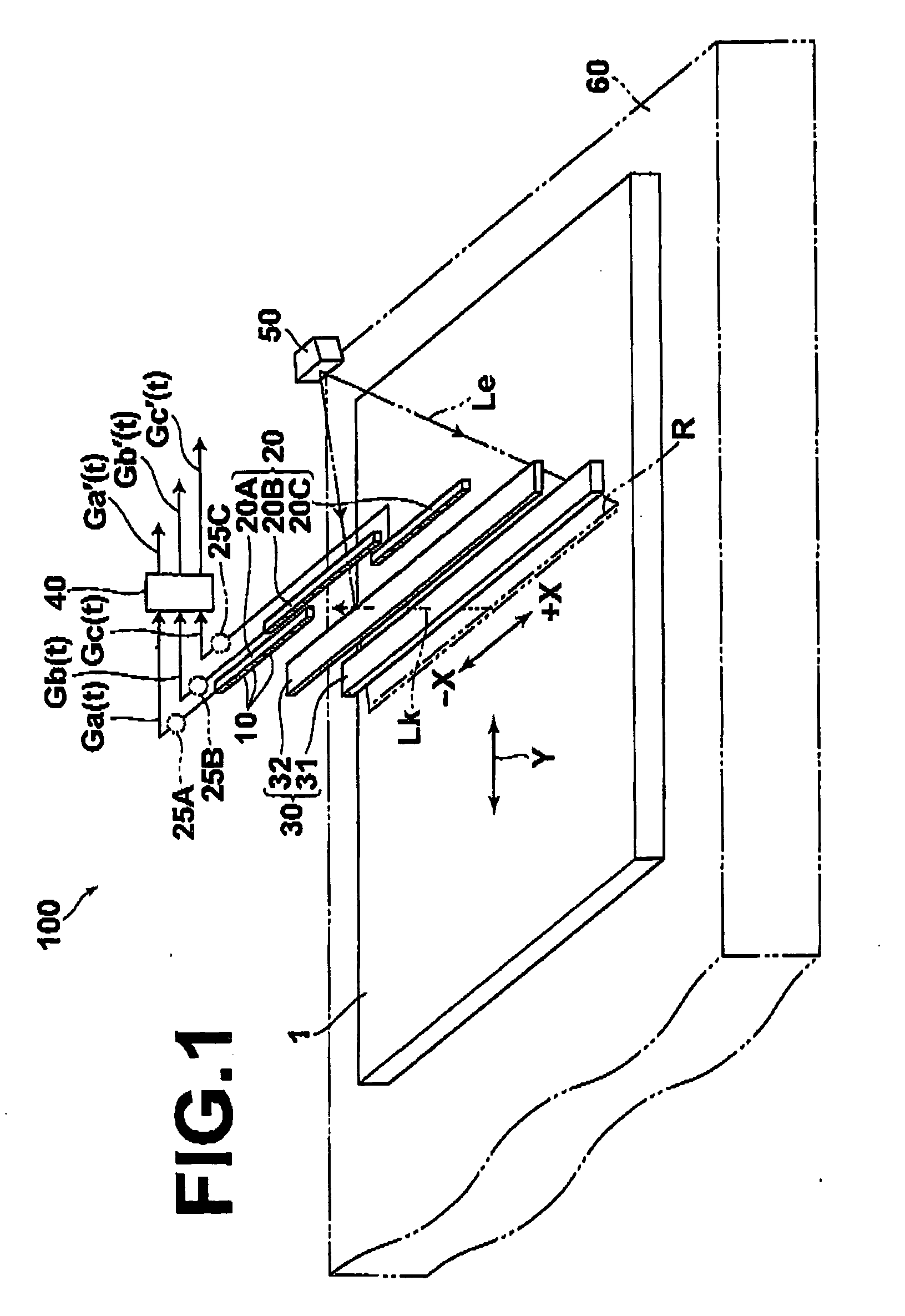
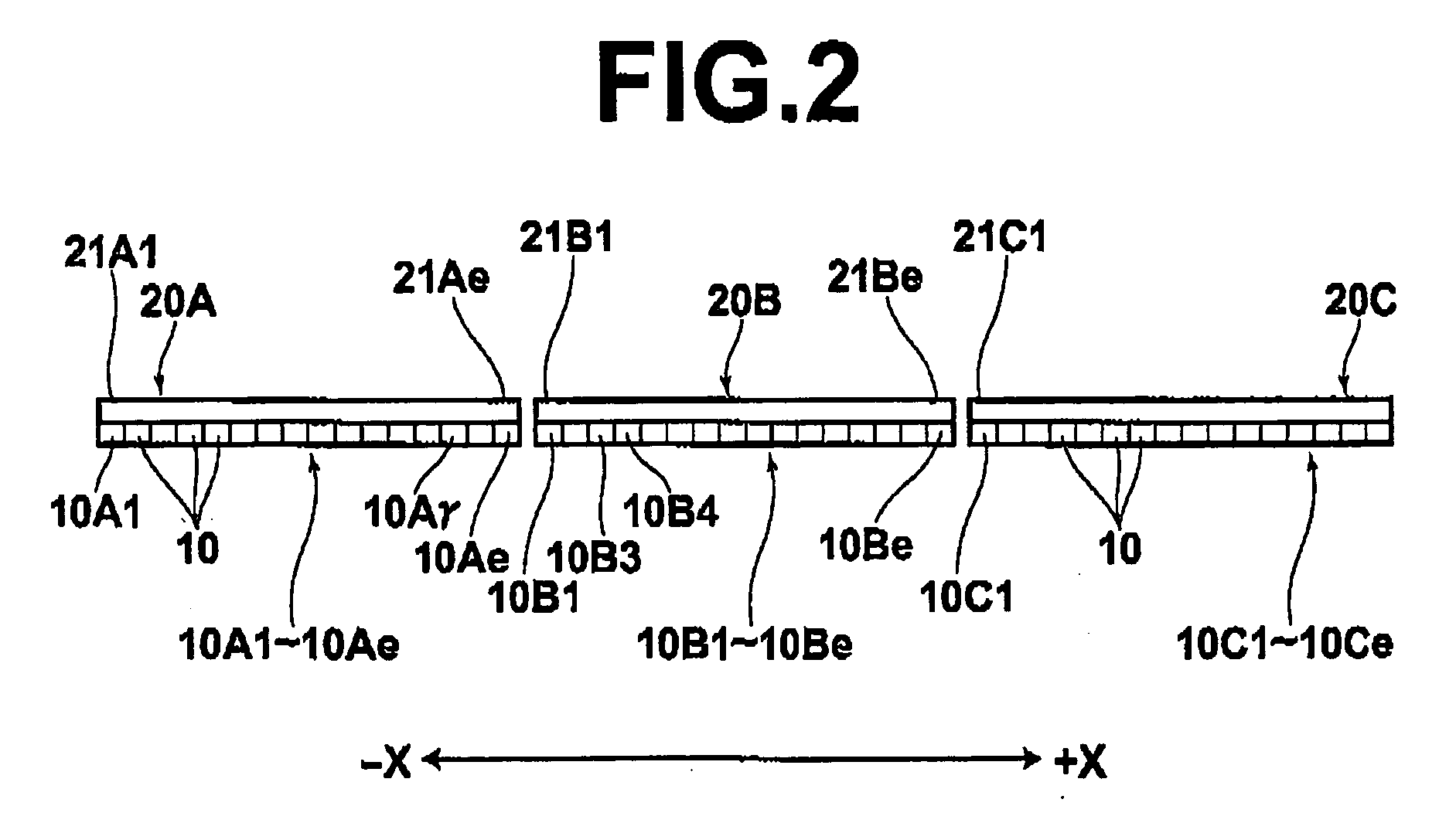
[0086] Preferred embodiments of the present invention will be described with reference to the drawings, hereinbelow. FIG. 1 is a perspective view showing in brief an arrangement of a radiation image read-out system to which a method of correcting image data in accordance with an embodiment of the present invention is applied, FIG. 2 is a view showing a plurality of line sensors arranged without overlap, FIG. 3 is a view showing the image data value output from each photo-sensor, FIG. 4 is a view showing correction of the image data value, and FIG. 5 is a perspective view showing a modification of the radiation image read-out system to which the method of correcting image data is applied. In FIGS. 3 and 4, the abscissa X represents the position of photo-sensors forming the line sensor, and the ordinate W represents the image data value output from the photo-sensor in correspondence to the position of each of the photo-sensors. In FIGS. 3 and 4, the direction toward the line sensor 20...


PUM


Abstract

In a method of correcting image data output from each of photo-sensors forming a plurality of line sensors arranged in a first direction, one of the plurality of line sensors is determined as a reference line sensor, and another line sensor adjacent to the reference line sensor is determined as an object line sensor to be corrected. A larger correction value is given to the image data value output from photo-sensor in the object line sensor nearer to an end of the reference line sensor facing the object line sensor.

Description

BACKGROUND OF THE INVENTION [0001] 1. Field of the Invention [0002] This invention relates to a method of and a system for correcting image data output from each of photo-sensors forming a line sensor a plurality of which are arranged in one direction and a computer program for causing a computer to execute the method of correcting image data. [0003] 2. Description of the Related Art [0004] There has been known a system in which image data representing an image on an object is obtained by causing a long line sensor comprising a plurality of line sensors each of which comprises a number of photo-sensors arranged in one direction and which are arranged in said one direction to scan the original in a direction perpendicular to said one direction. (See Japanese Unexamined Patent Publication No. 2004-166151) [0005] Since the line sensors described above are formed by forming a plurality of photo-sensors on same substrates, the light receiving characteristics of the line sensors differ fr...

Claims


Application Information

Patent Timeline
IPC IPC(8): G06K9/40
CPCH04N1/387
Inventor KUWABARA, TAKAOKUWABARA, TAKESHI
Owner FUJIFILM CORP
Learn More