Osteosynthesis plate set

a technology of osteosynthesis and plate, applied in the field of osteosynthesis set, can solve the problems of lack of bone support and fixing points for bone screws, loss of mechanical stability of plate osteosynthesis, and time-consuming plate adaptation, and achieve the effect of stable and more rotationally rigid splinting, and better fixing of bone fragments

Active Publication Date: 2006-11-23
SYNTHES USA
View PDF12 Cites 92 Cited by
  • Summary
  • Abstract
  • Description
  • Claims
  • Application Information

AI Technical Summary

Benefits of technology

[0017] This object is achieved by the use of a bone plate system comprising at least a first bone plate having upper and lower surfaces and configured and dimensioned for attachment to bone and at least a second bone plate having upper and lower surfaces and configured and dimensioned for attachment to bone. A total of at least four through-holes passing through the first and / or second bone plates from their upper surfaces to their lower surfaces are provided, the at least four holes configured and dimensioned for receiving bone screws in a plurality of different directions. The at least four through holes of the first and second bone plates are configured and dimensioned to accept bone screws in at least four different directions in space. At least one of the two bone plates has at least two holes configured and dimensioned for receiving bone screws substantially parallel to the joint axis, and at least one of the two bone plates has at least one hole which is configured and dimensioned to receive a bone screw substantially perpendicular to the joint axis. The novel formation of the two osteosynthesis plates results in more complete penetration of the bone tissue with bone screws, so that better fixing of the bone fragments can be achieved even with fewer bone screws. Moreover, laterally located bone fragments can also be fixed, and overall substantially more stable and more rotationally rigid splinting is possible.

Problems solved by technology

1) Non-specific pre-shaping of the plates requires complicated bending of the plates, which may lead to a loss of mechanical stability of the plate osteosynthesis.
Complicated adaptation of the plates is moreover time-consuming.
Since the plates are not optimized for the distal humerus, lack of bone support and fixing points for the bone screws may result;
3) A disadvantage of a plate system having a parallel plate configuration is that it requires that all bone fragments lie approximately in a planar, relatively flat space between the two osteosynthesis plates or can be contacted there by inserted bone screws.
If, however, bone fragments lie slightly outside this relatively narrow, planar space, they cannot be contacted by the known osteosynthesis plates or by the bone screws in the known osteosynthesis plates and held with reduction.
Moreover, the inventors observed that the one-row osteosynthesis plate may have only very little stability to tilting out of the connecting axial plane of the holes.
Accordingly, the possibility of loading the bone provided with the plate may therefore be greatly limited.
4) A right-angled plate arrangement ensures stability to tilting but lacks the possibility for screw engagement at an obtuse angle between the bone screw which was introduced through the lateral plate and between the bone screws which were introduced through the medial plate.
Systems which are on the market and correspond to this description may disadvantageously come to rest in the region of the points of action of the tendons and thus possibly disturb the function of the elbow.
Moreover, the known plates for osteosynthesis do not permit sufficient fixing by the distal block on the medial side.

Method used


Image

  • Osteosynthesis plate set
  • Osteosynthesis plate set
  • Osteosynthesis plate set

Examples


Embodiment Construction

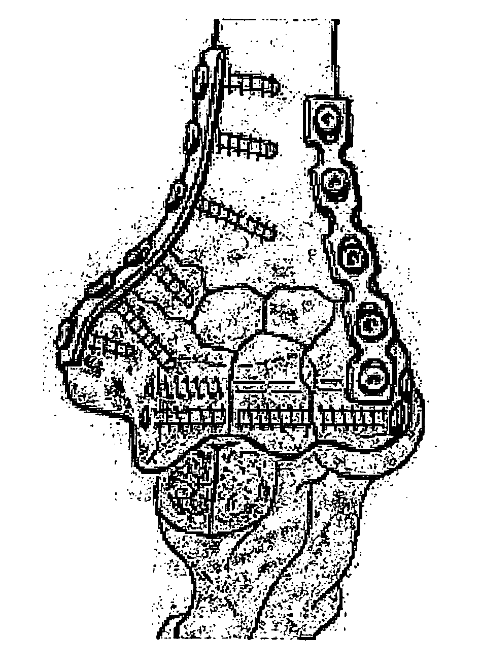
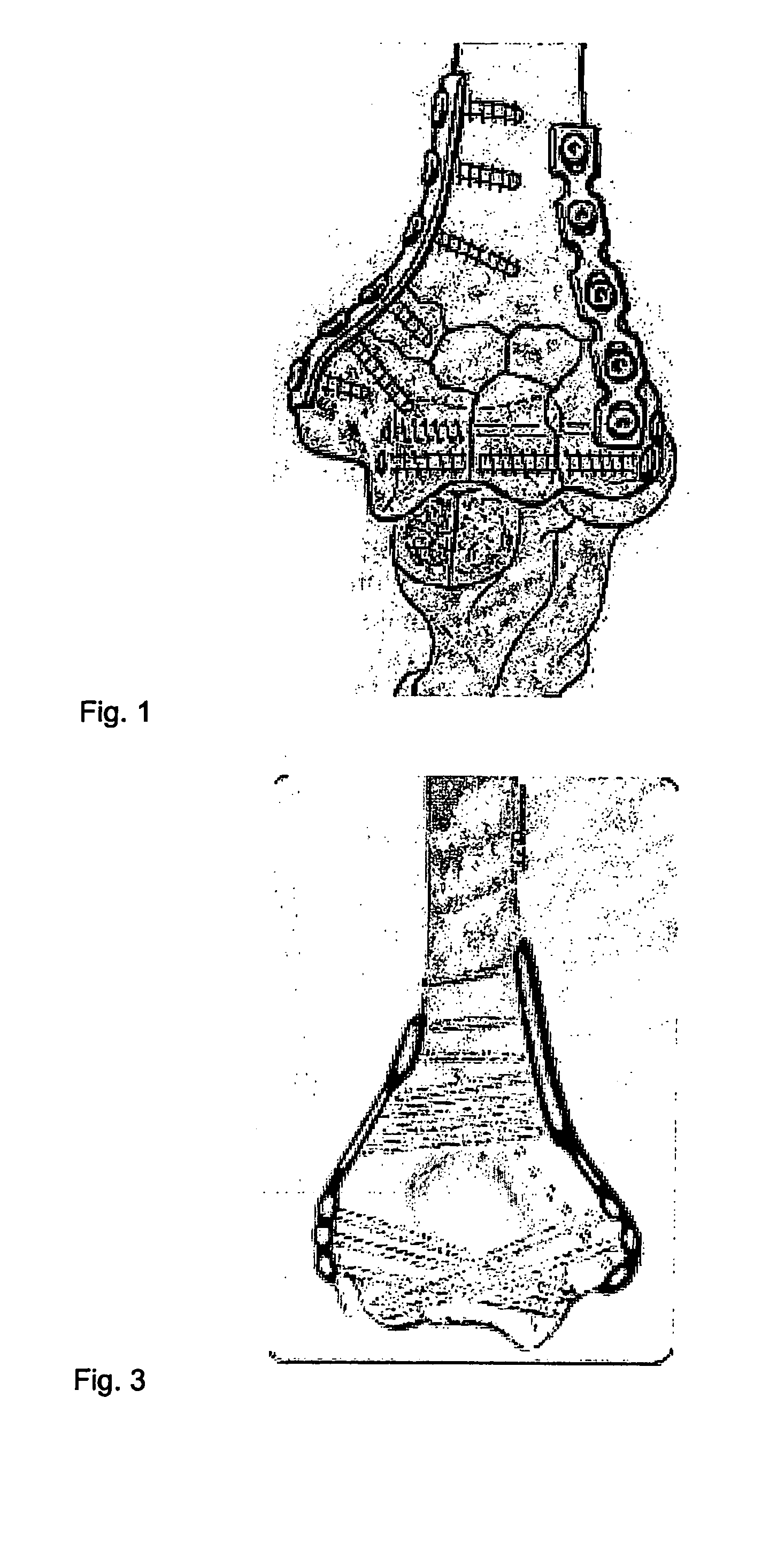
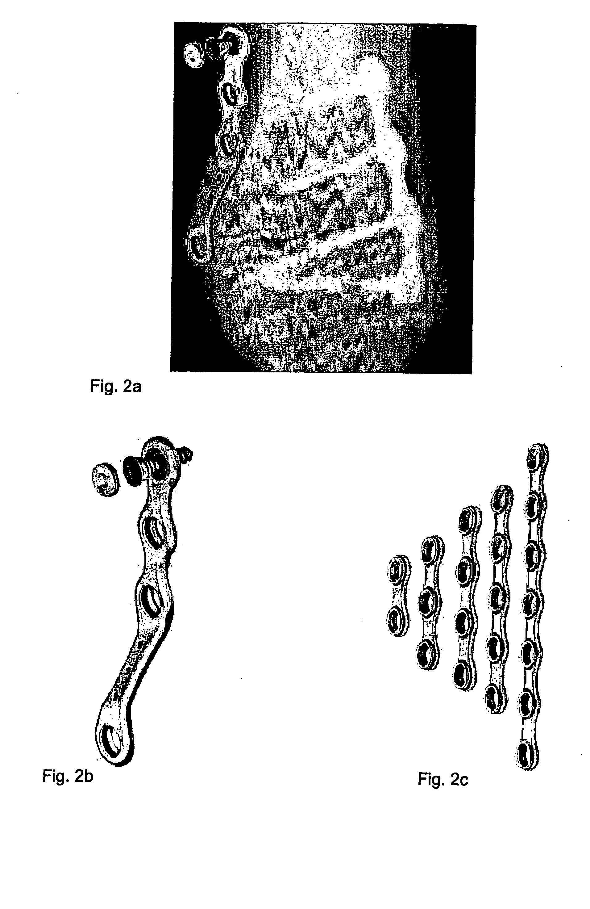
[0052]FIGS. 1-5 show the solutions available today on the market. FIGS. 6, 7, 11 and 12 show osteosynthesis plate sets 2g, 2h, 2i according to the invention in the positioned state.

[0053]FIGS. 8-9 show two different osteosynthesis plates 2g, 2h of a set according to the invention, and FIG. 10 shows a variant 2i of the design according to FIG. 9 without a tab.

[0054]FIGS. 6 and 7 show various hole shapes 3a, 3b, 3c in the osteosynthesis plates 2h and 2i, and FIGS. 6-7 and 11-12 show the preferred position of the osteosynthesis plates 2g, 2h, 2i on the bone 1.

[0055] As is evident from the diagrams in FIG. 6 and 11, drilled holes 3a, 3b, 3c lie along axes which intersect approximately at right angles with comparable axes of the drilled holes 3a, 3b, 3c of the respective other osteosynthesis plate 2h, 2g. In addition, further holes 3b which, owing to the tab-like curvature of the flange 4 are not parallel to the axes of the other holes 3a, 3b, 3c of the same osteosynthesis plate 2h ar...


PUM


Abstract

A set of at least two osteosynthesis plates (2g, 2h) for implantation, anatomical reduction and internal splinting of bone fragments, in particular after fractures of the distal humerus. The two osteosynthesis plates (2g, 2h) according to the invention are provided with drilled holes (3a, 3b, 3c) which are arranged or formed so that the bone crews (12) passing through them come to rest in different directions in space, so that bone screws (12) can pass more completely than in the past through the bone space of the splinted bone (1).

Description

RELATED APPLICATION DATA [0001] The present application is a continuation of the U.S. National Stage designation of co-pending International Patent Application No. PCT / IB2003 / 05243, filed Nov. 18, 2003, the entire content of which is expressly incorporated herein by reference thereto.FIELD OF THE INVENTION [0002] The invention relates to an osteosynthesis set comprising at least one first and at least one second osteosynthesis plate having altogether at least four drilled holes for bone screws. BACKGROUND OF THE INVENTION [0003] Osteosynthesis plates for implantation, anatomical reduction and internal splinting of bone fragments after fractures are widely known. A bone plate for osteosynthesis could be of a general type, which means that the bone plate is not adapted to a certain anatomical position, or it might be of a specific type, which means that the properties of the bone plate have been adapted in order to correspond to a specific type of an anatomical position. For the elbow...

Claims


Application Information

Patent Timeline
Patent Type & Authority Applications(United States)
IPC IPC(8): A61F2/30A61B17/80
CPCA61B17/8061
Inventor KOHUT, GEORGESINAUEN, BEATNORSTROM, JOANNAANDERMATT, DANIEL
Owner SYNTHES USA
Why Eureka
Try Eureka