Self-start synchronous motor, method for manufacturing the same and compressor
a synchronous motor and self-starting technology, applied in the direction of synchronous motors, rotors, cage rotors, etc., can solve the problems of permanent magnet deterioration and difficulty in further enhancing efficiency, and achieve the effect of preventing permanent magnet deterioration and high degree of efficiency
- Summary
- Abstract
- Description
- Claims
- Application Information
AI Technical Summary
Benefits of technology
Problems solved by technology
Method used
Image
Examples
embodiment 1
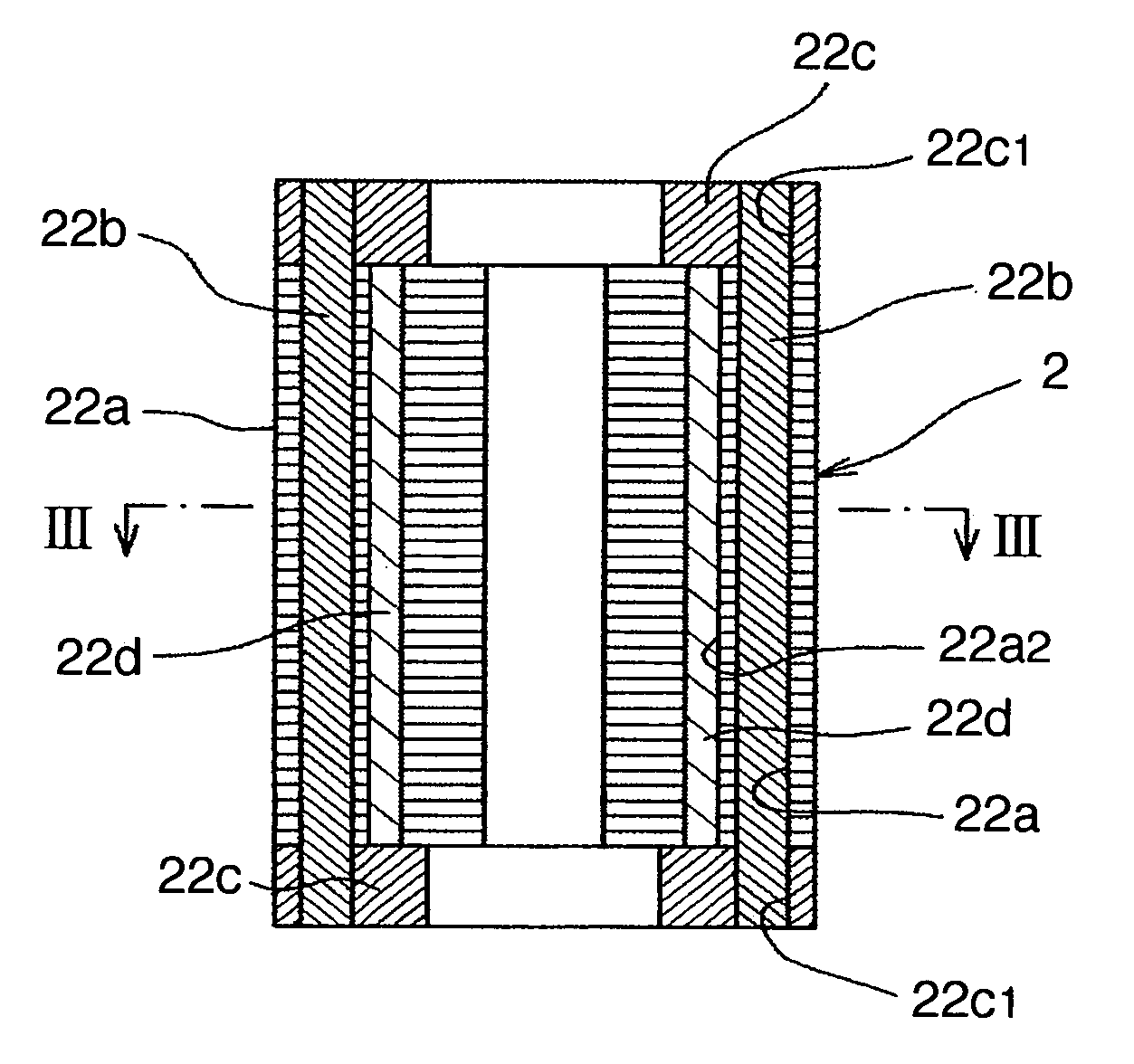
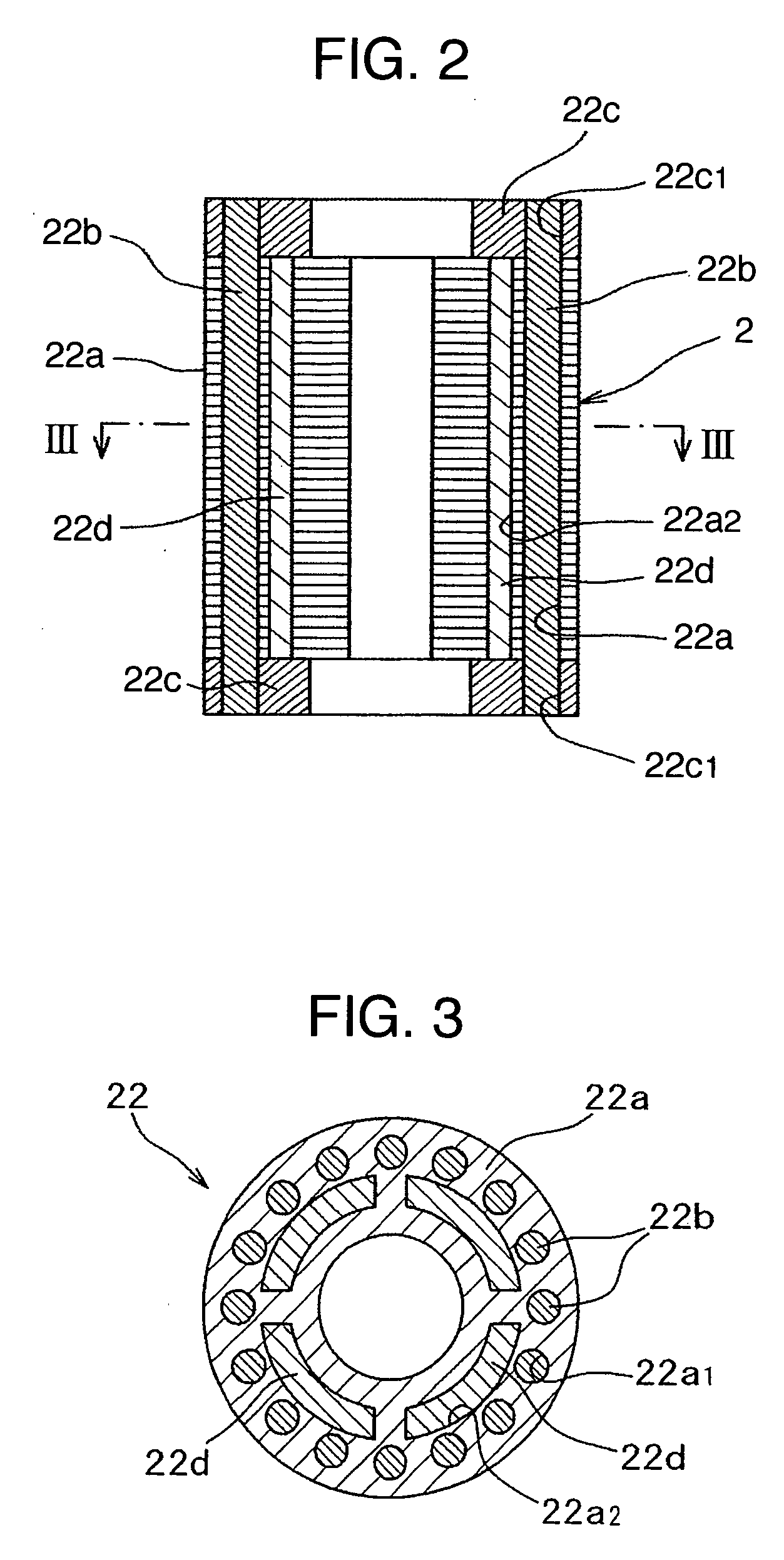
[0036] A self-start synchronous motor, a method of manufacturing thereof and a compressor according to a first embodiment of the present invention will be hereinbelow explained with reference to FIGS. 1 to 4.
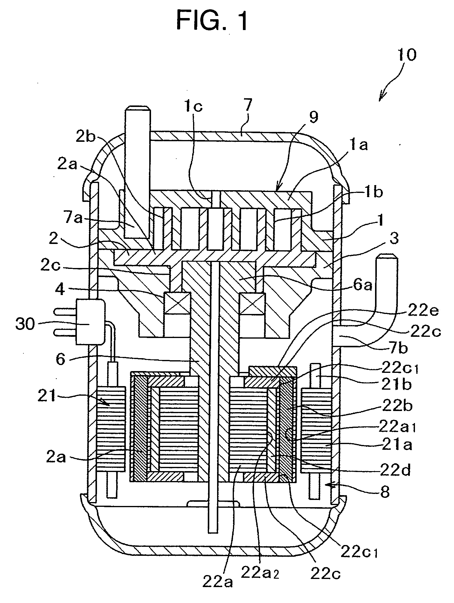
[0037] First, the overall configuration of a compressor 10 in the first embodiment will be explained with reference to FIG. 1. FIG. 1 is a longitudinal sectional view illustrating a compressor incorporating a self-start synchronous motor in the first embodiment.
[0038] A closed container 7 has a sealed structure, enclosing therein a compression mechanism portion 9 composed of a stationary scroll 1, an orbiting scroll 2, a frame 3 and the like, and the self-start synchronous motor 8 composed of a stator 21, a rotor 22 and the like, and a lubricant (which is not shown). The compression mechanism portion 9 and the self-start synchronous motor 8 are arranged up and down. The closed container 7 can bear against a high pressure of compressed fluid (refrigerant gas used for refrigerat...
second embodiment
[0060] Next, explanation will be made of a second embodiment according to the present invention with reference to FIGS. 5A to 5C. FIGS. 5A to 5C are perspective process views for explaining a method of manufacturing a self-start synchronous motor according to the second embodiment of the present invention. The configuration of the second embodiment is basically the same as that of the first embodiment, except those which will be explained hereinbelow. Thus, explanation duplicated with that of the first embodiment will be omitted.
[0061] In the second embodiment, at first, as shown in FIG. 5a, the conductor bars 22b and one of the end rings 22c are previously integrally incorporated with each other. Then, as shown in FIG. 5B, the conductor bars 22b of the thus integrally incorporated product are inserted through the circular slits 22a1 of the rotor core 22a, allowing the free end portions thereof to project from an end face of the rotor core 22a, and the projected portions of the con...
third embodiment
[0064] Next, explanation will be made of a third embodiment according to the present invention with reference to FIG. 6. FIG. 6 is a perspective process view for explaining a method of manufacturing a self-start synchronous motor according to the third embodiment of the present invention. The configuration of the third embodiment is basically the same as that of the first embodiment, except those which will be explained hereinbelow. Thus, explanation duplicated with that of the first embodiment will be omitted.
[0065] In the third embodiment, the conductor bars 22b and end rings 22c are made of copper or copper alloy, and the balance weight portion 22e is integrally incorporated with the end ring 22c by means copper die-casting or copper forging. Further, with the preparation of conductor bars having two different lengths, the end faces of the conductor bars 22b are exposed flush with the outer surface of the balance weight portion 22e and the outer surface of the end ring 22c where...
PUM
 Abstract
Description
Claims
Application Information
 - R&D
- Intellectual Property
- Life Sciences
- Materials
- Tech Scout
- Unparalleled Data Quality
- Higher Quality Content
- 60% Fewer Hallucinations
Browse by: Latest US Patents, China's latest patents, Technical Efficacy Thesaurus, Application Domain, Technology Topic, Popular Technical Reports.
© 2025 PatSnap. All rights reserved.Legal|Privacy policy|Modern Slavery Act Transparency Statement|Sitemap|About US| Contact US: help@patsnap.com


