Stator and method of forming the same

a stator and stator technology, applied in the direction of dynamo-electric machines, magnetic circuit rotating parts, magnetic circuit shape/form/construction, etc., can solve the problems of increasing the cost of welding equipment, troublesome to measure the angle of inclination of the engaging groove, and troublesome to judge the skew angl

Inactive Publication Date: 2006-11-30
TOYOTA IND CORP
View PDF7 Cites 17 Cited by
  • Summary
  • Abstract
  • Description
  • Claims
  • Application Information

AI Technical Summary

Problems solved by technology

However, since the outer circumferential surface of the stator core is a cylindrical surface, there has been a problem that it is troublesome to measure angle of inclination of the engaging grooves which are formed diagonally in the cylindrical surface.
When the angle of inclination of the grooves is measured by image processing, the angle of inclination differs between points of measurement of each groove, so that it is troublesome to judge the skew angle.
In this case, by so inclining the fixation groove

Method used


Image

  • Stator and method of forming the same
  • Stator and method of forming the same
  • Stator and method of forming the same

Examples


Embodiment Construction

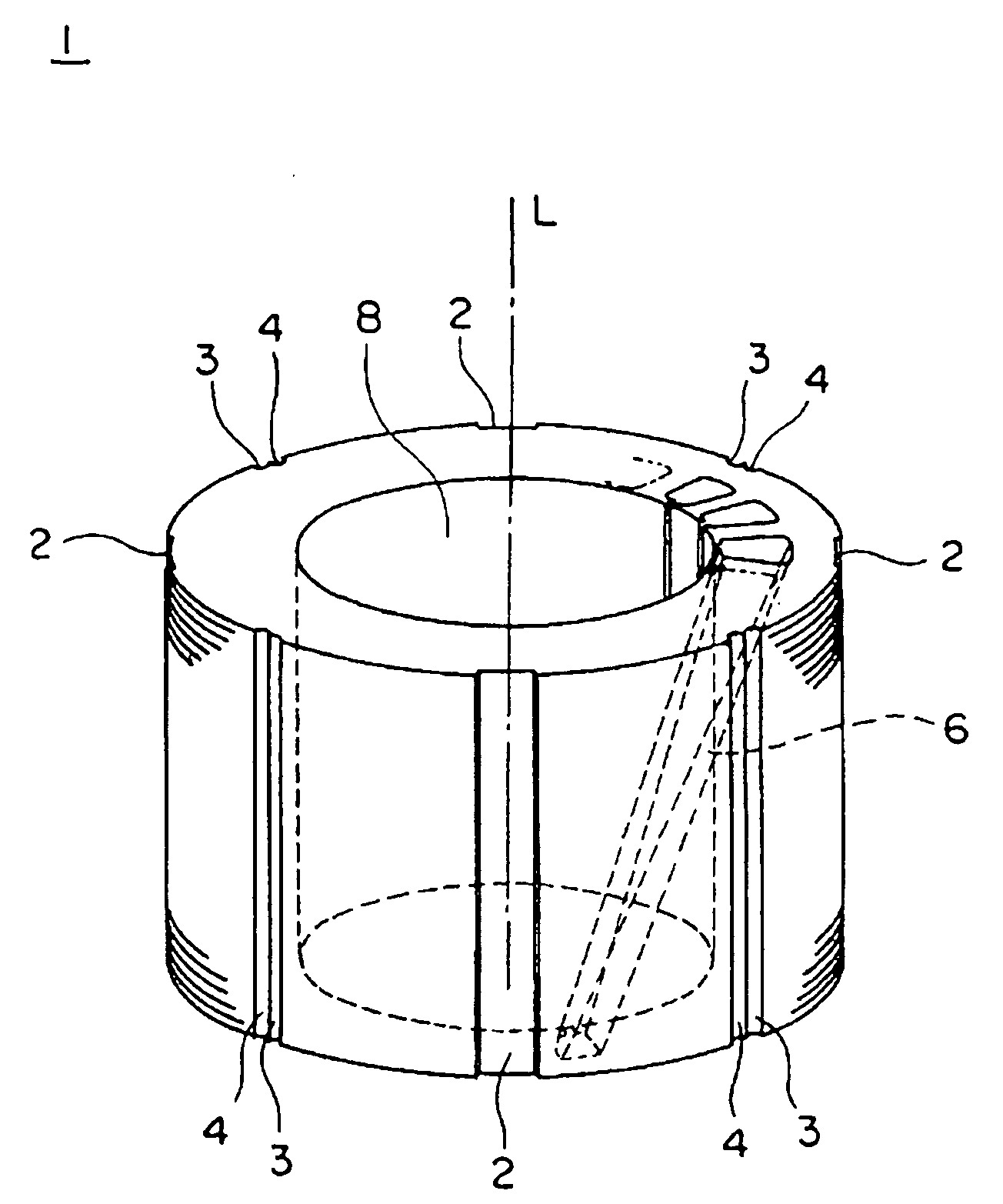
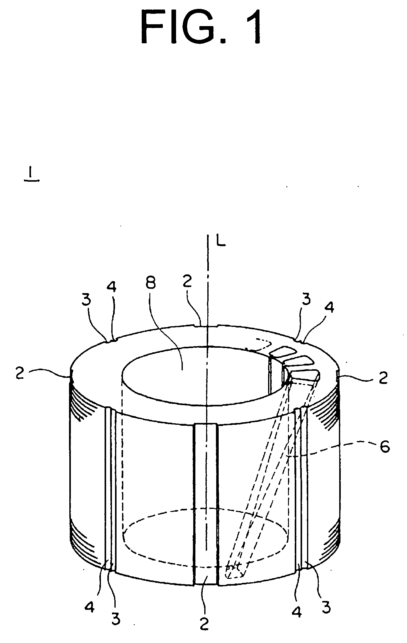
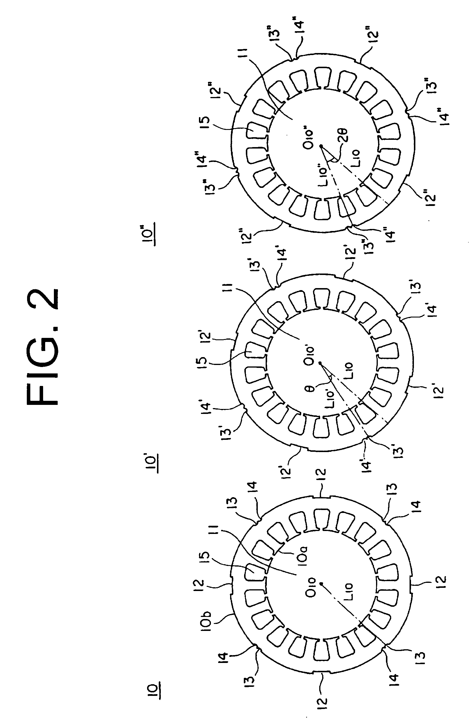
[0015] The following will describe embodiments of the present invention with reference to the accompanying drawings. FIG. 1 shows a stator core of a stator of the first embodiment. The stator core 1 is formed of a cylindrical shape and has a hollow portion 8 formed of a cylindrical shape. The stator core 1 is concentric with the hollow portion 8. An alternate long and short line shows an axis L of the stator core 1. The stator core 1 is so formed that a plurality of core sheets each of which has a disc-like shape are stacked. Three of the core sheets are shown in FIG. 2 and are identified by reference numbers 10, 10′ and 10″. The core sheet 10 is formed of a disc-like shape and has a hole 11 concentrically. The core sheet 10 has an inner edge 10a and an outer edge 10b thereof. A plurality of slot openings 15 are equally spaced in the inner edge 10a. Four recesses 12 are equally spaced in the outer edge 10b in the circumferential direction thereof. Adjacent recesses 12, 12 have a pai...


PUM


Abstract

A stator includes a cylindrical stator core and a coil. The stator core is formed by stacking a plurality of core sheets. The stator core has a groove formed in an outer circumferential surface thereof and a slot. The coil is inserted in the slot. The groove is located parallel to an axis of the stator core and the slot is skewed with respect to the axis.

Description

BACKGROUND OF THE INVENTION [0001] The present invention relates to a stator and a method of forming the stator. [0002] A conventional stator for use in an electric motor and a method of forming the stator are disclosed by Japanese Unexamined Patent Application Publication (KOKAI) No. 2001-8417 wherein a plurality of core sheets having holes with concentric circles are stacked to form a stator core. Each core sheet has a plurality of recesses formed in the inner edge thereof thereby to form a plurality of slots in the inner circumferential surface of the stator core. The slots are in parallel with an axis of the stator core, in which a coil is inserted. Each core sheet also has a plurality of recesses formed in the outer edge thereof thereby to form a plurality of engaging grooves in the outer circumferential surface of the stator core. The engaging grooves are in parallel with the axis of the stator core, with which an engaging tool is engaged for skewing the slots. When the tool w...

Claims


Application Information

Patent Timeline
IPC IPC(8): H02K1/00
CPCH02K1/16H02K2201/06H02K15/06H02K15/024
Inventor FUKASAKU, HIROSHIMERA, MINORUHORIBA, TATSUYA
Owner TOYOTA IND CORP
Why Eureka
Try Eureka