Motor manufacturing method

A manufacturing method and coil technology are applied in the field of inserting a coil into a motor iron core, so as to achieve the effect of shortening the length and increasing the coil insertion process.

Inactive Publication Date: 2005-03-16
AISIN AW CO LTD
View PDF3 Cites 11 Cited by
  • Summary
  • Abstract
  • Description
  • Claims
  • Application Information

AI Technical Summary

Problems solved by technology

[0010] The excessive protruding of the coil end of the coil 8 may increase the size of the entire motor in the axial direction after the coil is assembled to the stator core.

Method used


Image

  • Motor manufacturing method
  • Motor manufacturing method
  • Motor manufacturing method

Examples


Embodiment 1

[0192] use Figure 1 to Figure 15 A method of manufacturing a motor according to an embodiment of the present invention will be described.

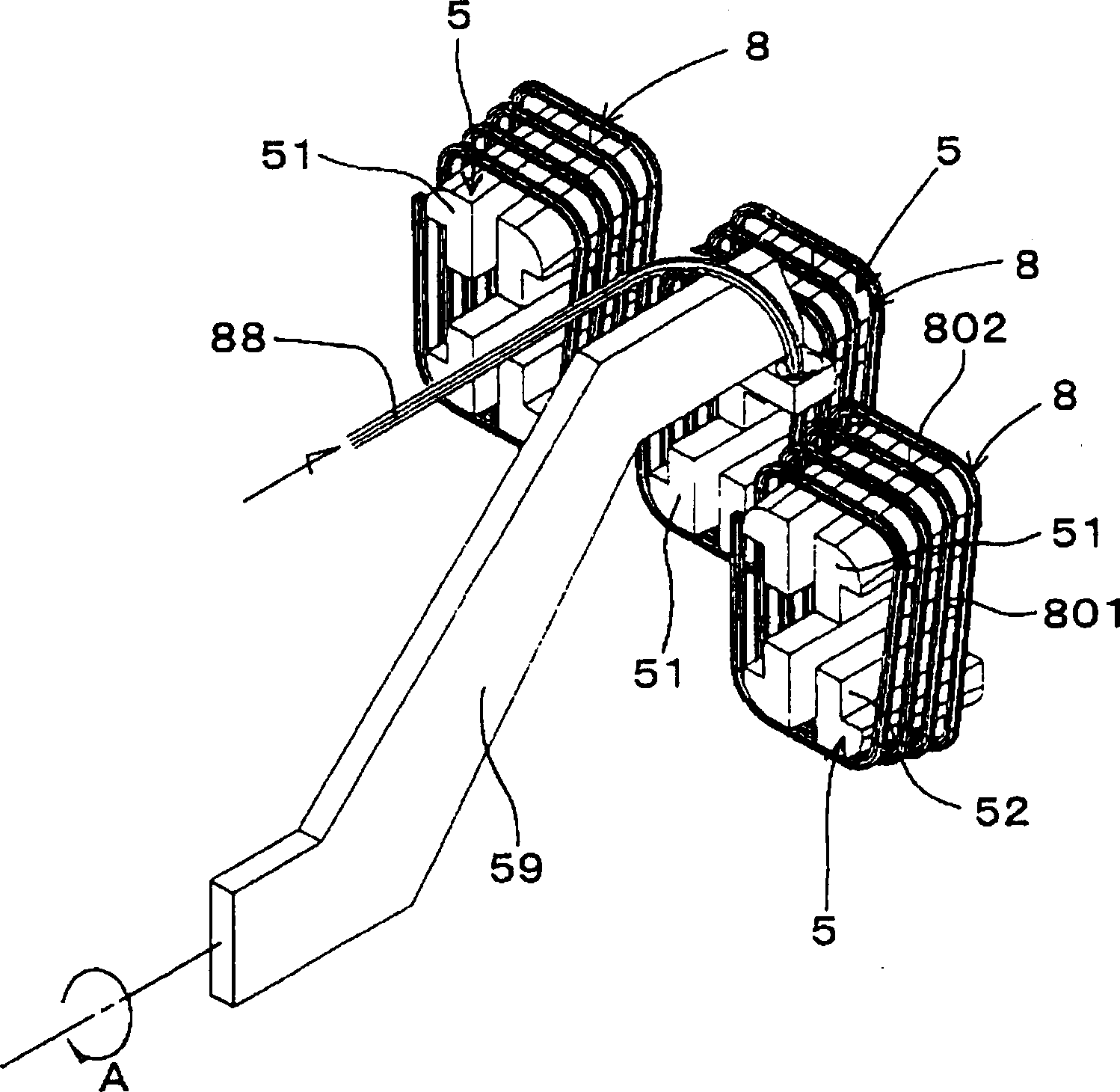
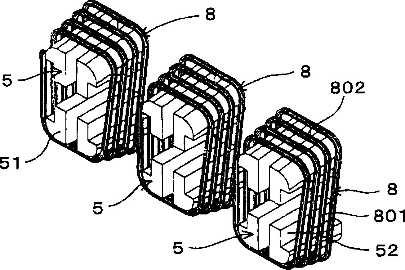
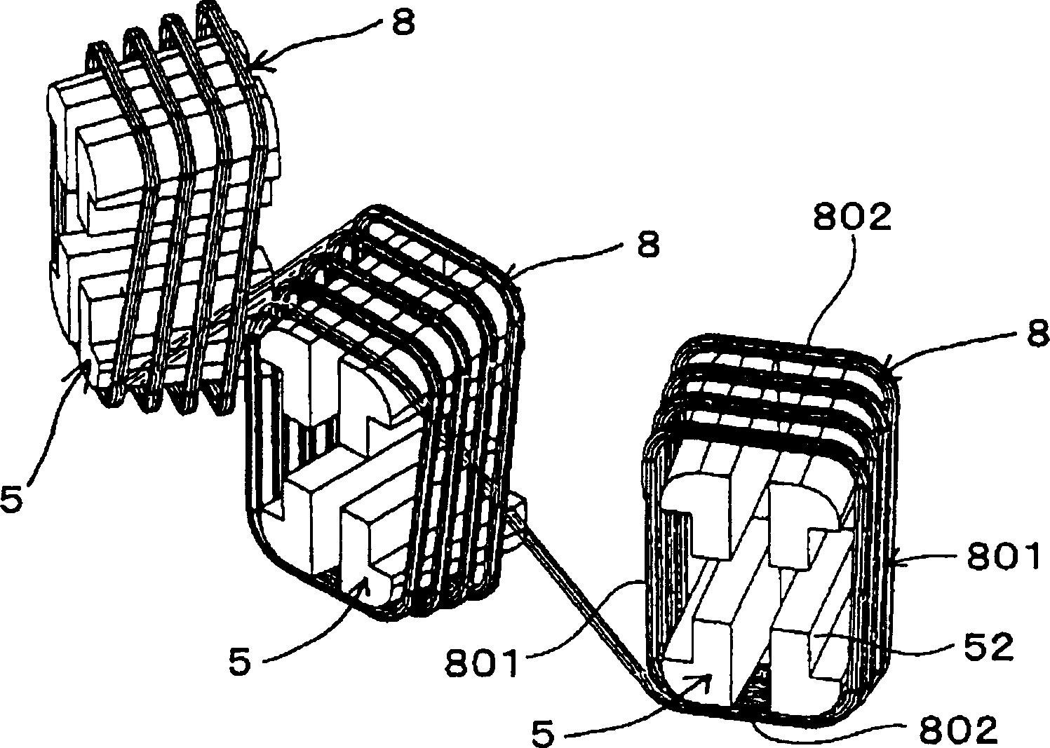
[0193] The motor manufactured by the motor manufacturing method of this example has an annular motor core (stator core) 1 ( Figure 9 ~ Figure 12 ), and has a three-phase (U-phase, V-phase, W-phase) coil group ( Figure 16 , Figure 17 ), the coil group of each phase is composed of a plurality of unipolar coils 8 constituting one pole, and each unipolar coil 8 straddles and passes through the two aforementioned slots 10 respectively, and is inserted and arranged in the aforementioned stator core 1, and belongs to different Parts of the coil ends 802 of the monopolar coils 8 of the phase coil group overlap each other in a state of being mounted on the stator core 1 .

[0194] The manufacturing method of this example includes a coil forming step and a coil inserting step.

[0195] The coil forming process is a process of forming a coil ...

Embodiment 2

[0259] In this example, as Figure 18 , Figure 19 As shown, an example of the coil insertion device for inserting the coil from the coil loading stand 2 to the stator core 1 in the first embodiment will be described in more detail.

[0260] The coil inserting device 9 of this example, as Figure 18 As shown, there is an upper plate portion 92 fixed by unillustrated pillars extending from the bottom plate portion 91, and a coil loading frame support table 93 on which the coil loading frame 2 is placed is provided on the upper portion.

[0261] The coil loading stand support 93 includes a flange portion 931 and a cylindrical central protrusion 932 having a smaller diameter than the flange portion 931 .

[0262] Further, the bottom plate portion 91 is provided with a plurality of first arms 94 arranged to swing about a fulcrum 941 and a plurality of second arms 95 arranged to swing about a fulcrum 951 . The first arm 94, as shown in the figure, has the insertion blade 3 at it...

Embodiment 3

[0273] In this case, such as Figure 20 Shown is another example of the above-mentioned insert blade.

[0274] That is, as shown in the figure, the insertion vane 302 of this example has a substantially L-shape and is composed of a base portion 303 extending in the horizontal direction and a vertical vane portion 304 extending in the vertical direction. The blocking surface 305 of the vertical blade portion 304 is set as a vertical surface. By moving the base portion 303 in the horizontal direction, the vertical blade portion 304 advances and retreats while keeping the stopper portion 305 vertical.

[0275] Using the insert blade 302, as Figure 20 As shown in (a), even when the coil insertion portion 801 is in contact with the coil insertion portion 801, at the moment when the insertion into the slot 10 of the stator core 1 is completed, the angle formed by the coil insertion portion 801 and the axial direction of the stator core 1 can be substantially reduced. Hold at 0°....


PUM


Abstract

A motor manufacturing method, comprising the steps of holding a plurality of single-pole coils by a coil holding means, arranging the plurality of single-pole coils so that the coil insert parts of the single-pole coils are opposed to the inner peripheral opening parts of slots and positioned generally parallel with each other in the axial direction of a motor core, moving the single-pole coils generally linearly toward the motor core so as to be disengaged from the coil holding means so that the moving routes of the adjacent single-pole coils before being inserted into the slots of the adjacent coil insert parts become parallel with each other or close with each other starting at the inner peripheral side toward the outer peripheral side thereof and that two coil insert parts of the single-pole coils start the movement simultaneously and the speeds thereof become the same.

Description

technical field [0001] The invention relates to a manufacturing method of a motor, in particular to a method of inserting a coil into the iron core of the motor. Background technique [0002] When manufacturing a motor having a stator formed by inserting coils into slots of a motor core such as a stator core or a rotor core, the method of inserting the coils is very important. Conventionally, various coil insertion methods or insertion devices have been proposed. [0003] In conventional coil insertion methods, for example, as disclosed in Patent Documents 1 to 3 below, a so-called inserting process has become the mainstream. [0004] An example of this conventional plug-in process will be briefly described as follows: Figure 66 , Figure 67 As shown, the annular stator core 1 is arranged in a horizontal state, and the coil 8 is also arranged in a substantially horizontal state below the axial direction. Then, a tool (not shown) is raised from below the coil 8 through th...

Claims


Application Information

Patent Timeline
Patent Type & Authority Applications(China)
IPC IPC(8): H02K15/085H02K15/04H02K15/06
CPCH02K15/0435H02K15/066H02K1/16
Inventor 桥本伸吾畔柳彻山口毅木户隆裕
Owner AISIN AW CO LTD
Why Eureka
Try Eureka