Spring constant calibration device

a constant calibration and spring technology, applied in the direction of electric/magnetic roughness/irregularity measurement, electric/magnetic measuring arrangement, instruments, etc., can solve the problem of typical worse fractional terms than for macroscale, and achieve the effect of a tighter, convenient and more accurate spring constant calibration

Inactive Publication Date: 2006-11-30
UK SEC FOR TRADE & IND & HER BRITANNIC MAJESTYS GOVERNMENT OF THE UK OF GREAT BRITAIN & NORTHERN IRELAND
View PDF17 Cites 13 Cited by
  • Summary
  • Abstract
  • Description
  • Claims
  • Application Information

AI Technical Summary

Benefits of technology

[0033] Preferably, the reference cantilever includes built-in piezoresistors that allow electrical monitoring of its mechanical resonant frequencies. This gives a useful indication of damage to the cantilever that would otherwise cause a calibration error. There are two possible uses of these piezoresistors. They may simply be used to monitor the fundamental frequency of the reference cantilever prior to AFM calibration; a change of 2% or more may represent a significant change in the mass or spring constant of the reference cantilever, indicating that it should be replaced. Also, these piezoresistors allow an electrical measurement of several modes of the reference cantilever while shaking the entire chip containing the reference cantilever using (for example) a piezo-actuated stage. Measurement of several mode frequencies allows one to deduce the thickness of the membrane from which the cantilever is constructed, and therefore calibrate the reference cantilever itself. This could also be done by external interferometric methods (e.g. the Doppler method described later) but an electrical measurement via the current through the two piezoresistors will be quicker and more convenient in most cases.
[0034] By using the reference cantilever of the present invention, higher precision in spring constant calibration can be achieved. In comparison with existing reference cantilevers, the precision could be as much as a factor of about ten greater.

Problems solved by technology

The need to find a way of eliminating uncertainties due to the limited manufacturing tolerance of the actuator is even more important here than it is in the case of the large inductive version; though microfabricated devices are made with excellent dimensional tolerances in absolute terms, in fractional terms these are typically worse than for macroscale devices.

Method used


Image

  • Spring constant calibration device
  • Spring constant calibration device
  • Spring constant calibration device

Examples


Embodiment Construction

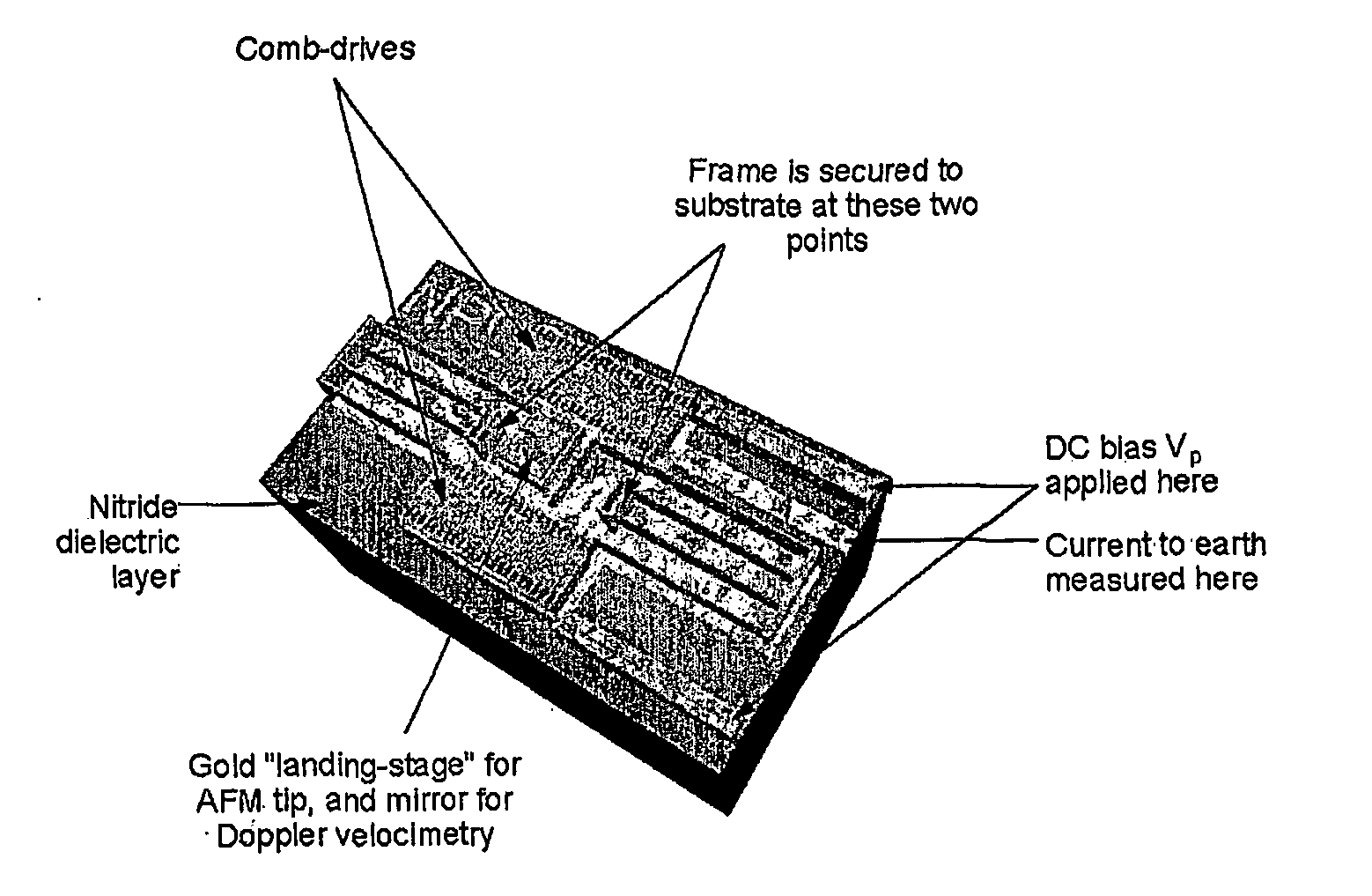
[0067]FIG. 1 is a three-dimensional computer model of a calibration device according to an embodiment of the present invention. The area shown is 980 by 560 microns. Dimensions perpendicular to the plane have been expanded by a factor of 20 for clarity.

[0068] In this embodiment, the Watt balance principle is applied in an entirely different context. The calibration device includes a microfabricated capacitive Watt balance for use in AFM spring-constant calibration.

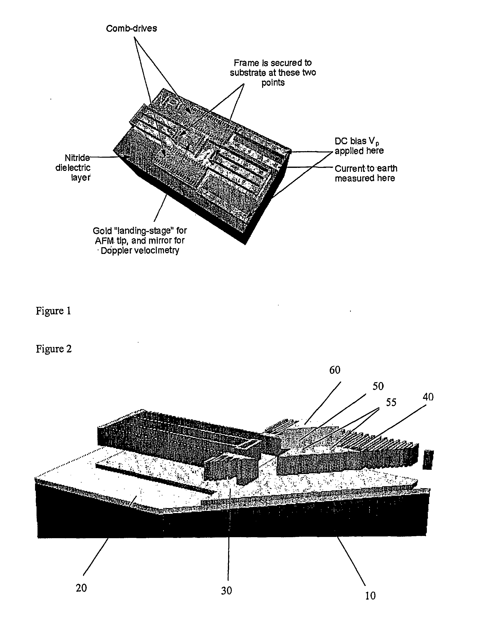
[0069]FIG. 2 is a cross section taken diagonally across the calibration device of FIG. 1 The measurement of the spring-constant of these two legs represents the calibration required.

[0070] In this embodiment, the substrate 10 is a 250 microns thick Si layer. There is then a silicon nitride layer 20 about 0.5 microns thick followed by a layer 30 of highly-doped (and therefore conductive) polycrystalline silicon. Comb drives 40 (one of which is illustrated in FIG. 2, although there could be any number) are also formed fro...


PUM


Abstract

A calibration device is disclosed. A platform has a substantially planar surface suitable for the landing of an AFM cantilever tip, one or more supporting legs arranged to provide sprung resistance to the platform and a capacitive sensor for measuring the combined spring constant of the one or more supporting legs with respect to displacement substantially perpendicular to said substantially planar surface.

Description

FIELD OF THE INVENTION [0001] The present invention relates to a calibration device suitable for calibrating small force measuring devices. In particular, the present invention relates to a calibration device in which accurate measurements under, and traceable to, the SI system can be obtained. BACKGROUND OF THE INVENTION [0002] Measurements of small forces, in the nanonewton and piconewton range, have become important in recent years due to the widespread use of the Atomic Force Microscope (AFM) and associated instruments. There is a need to measure such small forces accurately, for example, protein-protein interactions or materials properties via the small force applied to an indenting tip. [0003] Accuracy is rarely mentioned for AFM force measurements. AFMs measure displacement accurately, and are calibrated quite easily using step-height standards. Some AFM instruments even incorporate laser interferometry to make traceable height measurements. [0004] The quantification of inter...

Claims


Application Information

Patent Timeline
Patent Type & Authority Applications(United States)
IPC IPC(8): G01R35/00G01B7/34G01Q10/00G01Q40/00G01Q60/24
CPCG01Q40/00B82Y35/00
Inventor CUMPSON, PETER J.
Owner UK SEC FOR TRADE & IND & HER BRITANNIC MAJESTYS GOVERNMENT OF THE UK OF GREAT BRITAIN & NORTHERN IRELAND
Why Eureka
Try Eureka