Magnifier Having Slideably Mounted Camera

a technology of magnifier and camera, which is applied in the field of magnification devices, can solve the problems of heavy and cumbersome use of conventional magnifiers for people with low vision, and the use of conventional magnifiers is difficult, and achieves the effects of easy slide over any flat object, reduced manufacturing costs, and reduced manufacturing costs

Active Publication Date: 2006-11-30
FREEDOM SCI
View PDF25 Cites 17 Cited by
  • Summary
  • Abstract
  • Description
  • Claims
  • Application Information

AI Technical Summary

Benefits of technology

[0015] An important advantage of the novel portable magnifier is that it has a low profile and slides easily over any flat object to be magnified.
[0016] Another important advantage is that the profile of the magnifier is fixed, there being no need to adjust the height of the magnifier to achieve differing amounts of magnification.
[0017] Another advantage lies in the ability of the magnifier to provide greater magnification by sliding a camera in a horizontal plane in a first direction and less magnification by sliding the camera in a horizontal plane in a second direction opposite to said first direction.

Problems solved by technology

Conventional magnifiers for use by people with low vision are heavy and cumbersome to use.
Some conventional magnifiers are hard to use because a user must hold them in spaced relation to the object being magnified.

Method used


Image

  • Magnifier Having Slideably Mounted Camera
  • Magnifier Having Slideably Mounted Camera
  • Magnifier Having Slideably Mounted Camera

Examples


Embodiment Construction

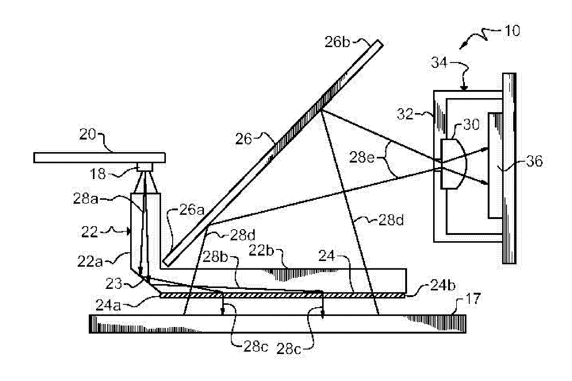
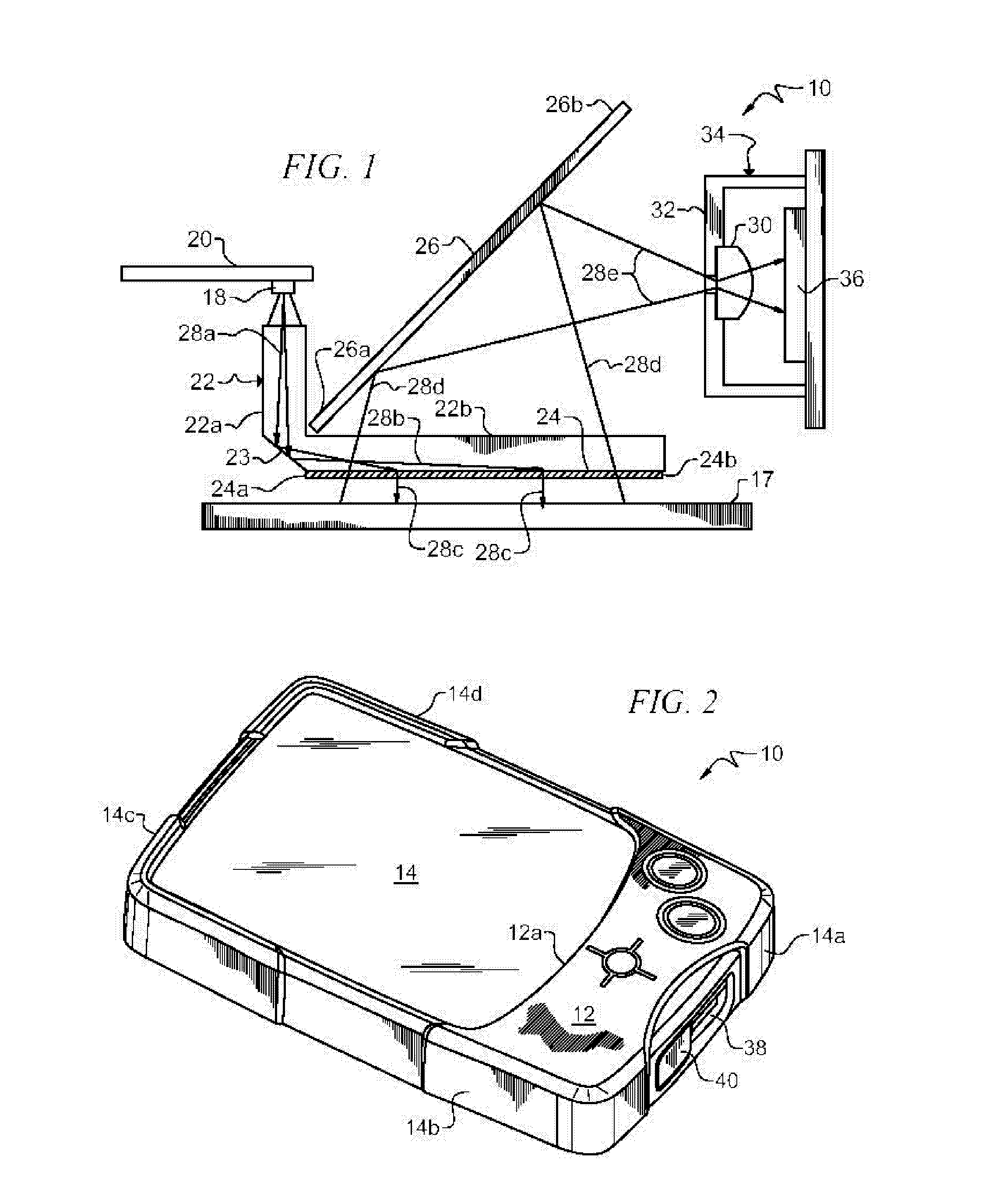
[0024] Referring now to FIGS. 1-4, it will there be seen that an illustrative embodiment of the invention is denoted as a whole by the reference numeral 10.

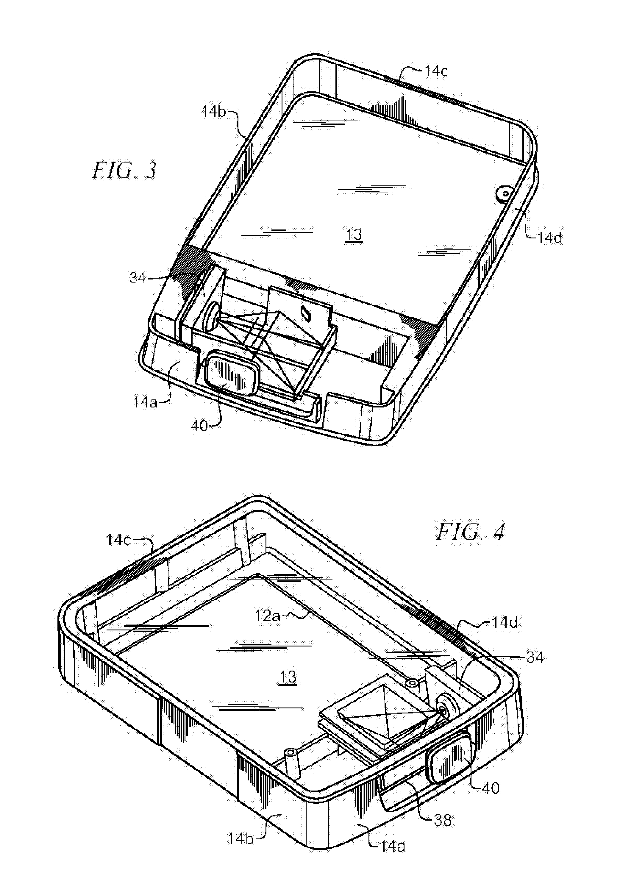
[0025] Magnifying device 10 has a hollow, box-like structure. Top wall 12 has an opening 12a formed therein within which is mounted LCD display 14. Bottom wall 13 is transparent and is disposed parallel to top wall 12. Sidewalls 14a, 14b, 14c, and 14d interconnect top wall 12 and bottom wall 13. Bottom wall 13 is placed atop an object 17 to be magnified. Bottom wall 13 is smooth so that magnifying device 10 can slide atop object 17 with low frictional resistance as the user of the device uses it to read a page of text, for example.

[0026] Bottom wall 13 can be eliminated. In such an embodiment, the respective bottom edges of sidewalls 14a-d would be smooth so that they could slide over object 17 with low frictional resistance. However, dirt or other debris could enter into the hollow interior of magnifier 10 if bottom wall 13 is...


PUM

PropertyMeasurementUnit
angleaaaaaaaaaa
transparentaaaaaaaaaa
frictionaaaaaaaaaa

Abstract

A magnifier for use by people with low vision includes a large LCD display upon which an enlarged image appears. Light from an LED is directed in a first direction onto a deflection wall where it is deflected into a direction substantially orthogonal to the first direction. The deflected light impinges upon a diffuser that bends it so that it illuminates an object upon which the magnifier is placed. The light is then reflected by the object, through the diffuser, and onto a mirror positioned at an angle relative to the object. The mirror directs the light onto a camera lens and the lens focuses the light onto a sensor that drives the LCD display so that the image appears on the LCD screen. The camera is slideably mounted so the user can make the image larger or smaller by sliding the camera toward or away from the mirror, respectively.

Description

CROSS REFERENCE TO RELATED APPLICATIONS [0001] This application claims priority to U.S. Provisional Patent Application No. 60 / 595,003, entitled: “Portable Electronic Magnifier,” filed by the same inventors on May 26, 2005.BACKGROUND OF THE INVENTION [0002] 1. Field of the Invention [0003] This invention relates, generally, to magnification devices for people with low vision. More particularly, it relates to a portable magnification device that is placed a fixed distance from an object to be magnified. [0004] 2. Description of the Prior Art [0005] Conventional magnifiers for use by people with low vision are heavy and cumbersome to use. Some conventional magnifiers are hard to use because a user must hold them in spaced relation to the object being magnified. [0006] Other conventional magnifiers are easier to use because they need not be held all the time but the user must adjust the height thereof to provide the desired amount of magnification. The device thus has a high profile whe...

Claims


Application Information

Patent Timeline
Patent Type & Authority Applications(United States)
IPC IPC(8): F21V7/04A47F3/00A47B19/00G02F1/1335H03H9/00
CPCG02B6/0011H04N7/183G02B27/027G02B6/0025
Inventor RODRIGUEZ, CARLOS M.TUNKIS, WALDEMAR H.CONARD, TODDMURPHY, PATRICKDEAN, RONALD JOSEPHDAVIS, BRADLEY S.GOLDENBERG, MICHAEL
Owner FREEDOM SCI
Why Eureka
Try Eureka