Unlock instant, AI-driven research and patent intelligence for your innovation.

Method and apparatus for adaptive false contour reduction

Inactive Publication Date: 2006-11-30
SAMSUNG ELECTRONICS CO LTD +1
View PDF10 Cites 36 Cited by
  • Summary
  • Abstract
  • Description
  • Claims
  • Application Information

AI Technical Summary

Benefits of technology

[0015] An aspect of the present invention is to provide a method and apparatus for adaptive false reduction that removes a flat region from an input image to detect a contour reg

Problems solved by technology

As display devices are increasing in size in the digital television (DTV) era, an artifacts problem rises which did not appear in the past.
That is, there is no artifacts problem when images are displayed on a cathode ray tube (CRT) monitor or a small-sized TV, but various artifacts problems have come up with larger and wider TV screens in the DTV era.
However, the conventional Daly and Feng false contour removal method is applied to all pixels of an input image.
Thus, the method has a problem that an output image has edges or texture corresponding to signal components which are degraded to become blurry since the entire input image passes through the low-pass filter.
Further, the method has a problem since it can be applied only with limited conditions assuming that the bit depth of an input image is lower than the bit depth of an output image or knowing an original image prior to false contour occurrence due to quantization.
Further, the conventional false contour removal method can be properly applied when the causes of the false contour are known, and has limitations that false contour can not be precisely determined.
In particular, the Daly and Feng method can not be used as a proper false contour removal method at the time a difference between a value obtained through a low-pass filter and a re-quantized value is not enough for false contour removal.

Method used


Image

  • Method and apparatus for adaptive false contour reduction
  • Method and apparatus for adaptive false contour reduction
  • Method and apparatus for adaptive false contour reduction

Examples


Embodiment Construction

[0045] Hereinafter, the present invention will be described in detail with reference to the accompanying drawings.

[0046]FIG. 2 is a block diagram for showing an apparatus according to an exemplary embodiment of the present invention.

[0047] In FIG. 2, the apparatus has a flat region removal part 100, a false contour detection part 200, and smoothing part 300.

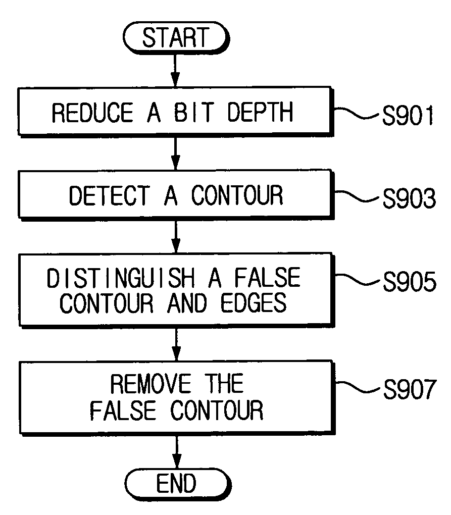
[0048] First, the flat region removal part 100 includes a bit depth reduction unit 110 and a contour detection unit 120, removes a flat region with homogeneous brightness values from a first input image Iij, and detects contour location information including a false contour and edges.

[0049] In detail, the flat region removal part 100 detects contour location information including a false contour and edges from a first input image by using a brightness value difference between the first input image and a second input image with a bit depth of the first input image reduced. Since the false contour corresponds to a noise compone...


PUM


Abstract

A method for adaptive false contour reduction includes: detecting contour location information by removing a flat region having certain brightness values from a first input image based on a bright value difference between the first input image and a second input image with a bit depth of the first input image reduced; detecting false-contour direction and location information by measuring directional contrast of the flat region-removed first image, and distinguishing the false contour area and an edge area out of the false contour location information based on the measured contrast; and smoothing the false contour area by using the false contour direction and location information, and removing the false contour from the first input image. Thus, a flat region can be automatically removed by using a brightness value difference between a bit depth-reduced image and an original input image and detect a false contour, thereby enhancing a precision degree of false contour detection. Further, signal components can be prevented from being degraded by performing smoothing over only a false contour.

Description

CROSS-REFERENCE TO RELATED APPLICATIONS [0001] This application claims benefit under 35 U.S.C. § 119 from Korean Patent Application No. 2005-46465, filed on May 31, 2005, the entire contents of which are incorporated herein by reference. BACKGROUND OF THE INVENTION [0002] 1. Field of the Invention: [0003] Methods and apparatuses consistent with the present invention relate to adaptive false contour reduction, and more particularly, to adaptive false contour reduction which is capable of removing a false-contour region by detecting the false-contour region of an input image and smoothing only the false-contour region. 2. Description of the Related Art: [0004] As display devices are increasing in size in the digital television (DTV) era, an artifacts problem rises which did not appear in the past. That is, there is no artifacts problem when images are displayed on a cathode ray tube (CRT) monitor or a small-sized TV, but various artifacts problems have come up with larger and wider TV...

Claims


Application Information

Patent Timeline
IPC IPC(8): G06K9/42
CPCG06T5/50G06T7/0083G06T2207/20012G06T5/002G06T5/20G06T2207/20192G06T7/12G06T5/70H04N5/21
Inventor KIM, JAE-SEUNGAHN, WONSEOKPARK, RAE-HONGLIM, BO RALEE, JI WON
Owner SAMSUNG ELECTRONICS CO LTD
Features
  • R&D
  • Intellectual Property
  • Life Sciences
  • Materials
  • Tech Scout
  • Unparalleled Data Quality
  • Higher Quality Content
  • 60% Fewer Hallucinations
Learn More