Method of producing a ferrule with an optical fiber

a technology of optical fiber and ferrule, which is applied in the direction of optics, instruments, optical light guides, etc., can solve the problems of deterioration of optical fiber characteristics, uneven application of bare optical fiber, and fear of external forces, so as to achieve control the effect of worsening of characteristics

Active Publication Date: 2006-11-30
FUJIKURA AUTOMOTIVE ASIA
View PDF1 Cites 35 Cited by
  • Summary
  • Abstract
  • Description
  • Claims
  • Application Information

AI Technical Summary

Benefits of technology

[0013] The present invention has been made in consideration of the above circumstances. An object of the invention is to provide a method of producing a ferru

Problems solved by technology

As a result, because of shrinkage of the adhesive occurring during a curing operation or due to changes in temperature and because of inclusion of bubbles in the adhesive, substantial stress acts on the part of the optical-fiber-insertion hole 114 in the vicinity of the tapered hole 115, thereby resulting in deterioration of characteristics of the optical fiber.
There is the fear that further deterioration of characteristics of the optical fiber may result due to damaging bends of the bare optical fiber 101.
As described above, when the end

Method used


Image

  • Method of producing a ferrule with an optical fiber
  • Method of producing a ferrule with an optical fiber
  • Method of producing a ferrule with an optical fiber

Examples


Embodiment Construction

[0040] With reference to the attached figures, exemplary embodiments of the present invention will now be described below. The described exemplary embodiments are intended to assist the understanding of the invention, and are not intended to limit the scope of the invention in any way.

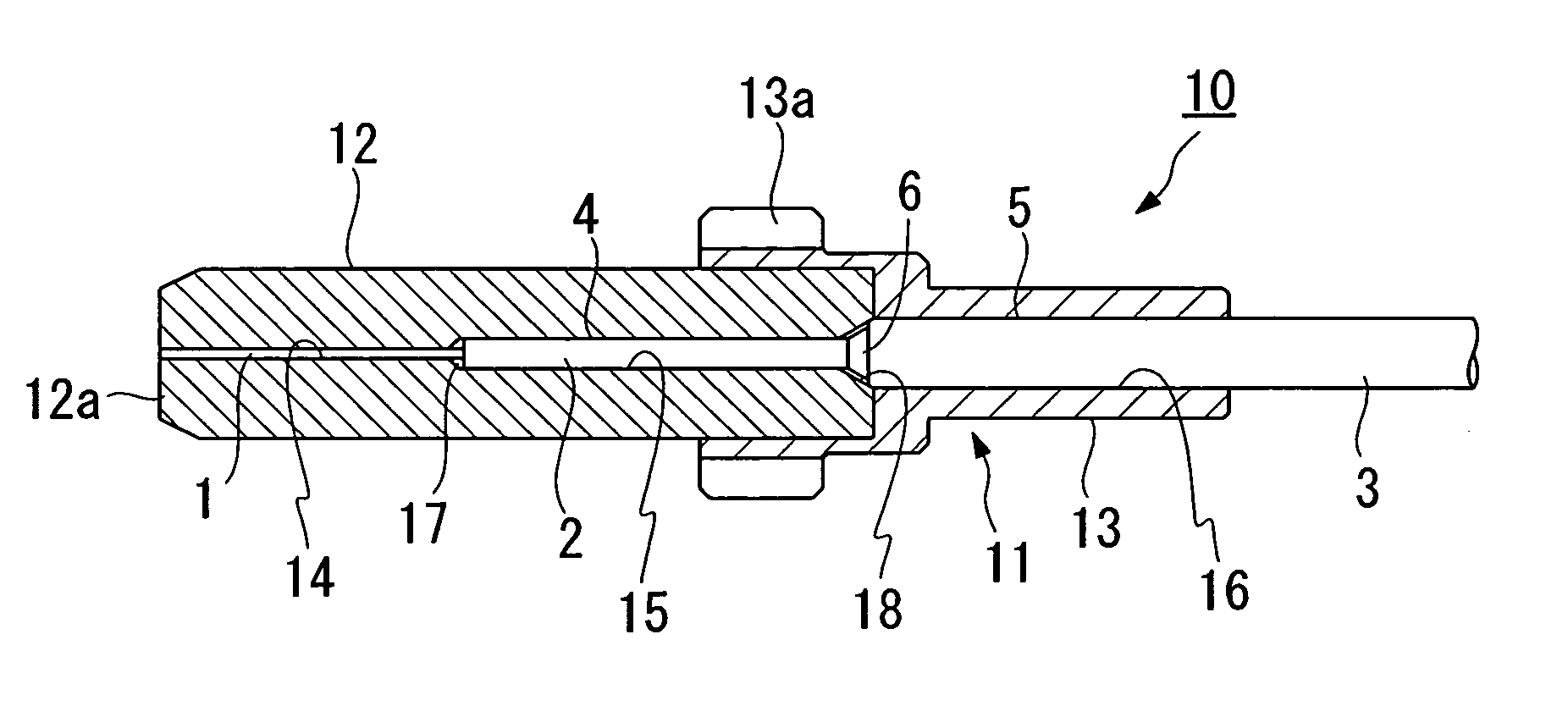
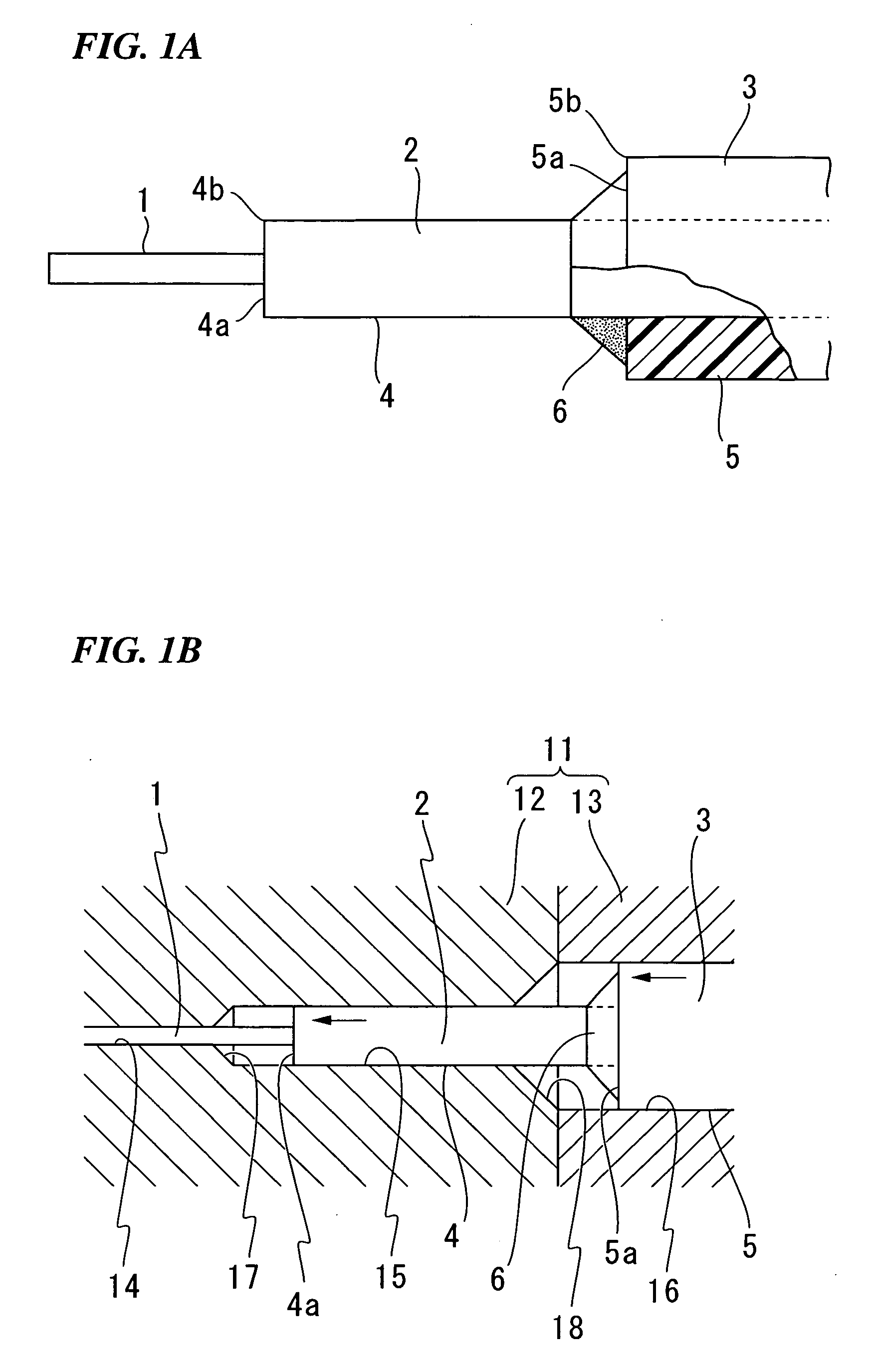
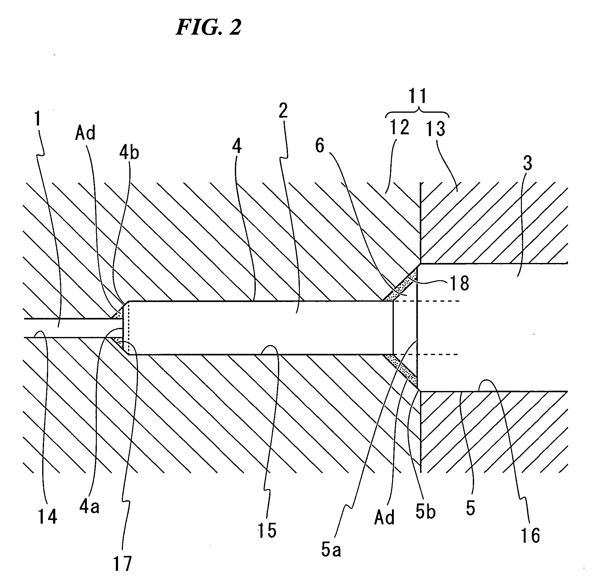
[0041]FIGS. 1A and 1B are views for explaining a method of producing a ferrule with an optical fiber according to the present invention. FIG. 1A is a fragmentary view showing a main portion of a coated optical fiber in which an adhesive portion is previously formed on an end of a reinforcing pipe by means of adhesive being cured. FIG. 1B is a longitudinal sectional view showing an appearance of the ferrule into which the coated optical fiber shown in FIG. 1A is inserted. FIG. 2 is a longitudinal sectional view showing a main portion of the ferrule with the optical fiber. Incidentally, in FIG. 1B, the adhesive portion for bonding an inner surface of a hole of the ferrule and a coated optical fiber is n...


PUM


Abstract

In a state in which a front end of a single-core fiber is passed through an end surface portion of a reinforcing pipe, an inner surface of the reinforcing pipe and an outer peripheral surface of the single-core fiber are glued together by means of adhesive. By using the same adhesive, an adhesive portion is formed by curing it so as to protrude and taper from the end surface portion of the reinforcing pipe toward the front end of the single-core fiber. Thereafter, a coated optical fiber formed with the adhesive portion is inserted in a ferrule until an end surface portion of the coating of the single-core fiber abuts against the first tapered hole and until the end surface portion of the reinforcing pipe abuts against the second tapered hole. Then, the optical fiber is glued in the ferrule by means of adhesive.

Description

CROSS-REFERENCE TO RELATED APPLICATIONS [0001] This application is based upon and claims the benefit of priority of Japanese Patent Application No. 2005-159599, filed at the Japanese Patent Office on May 31, 2005, the disclosure of which is incorporated herein in its entirety by reference. BACKGROUND OF THE INVENTION [0002] 1. Field of the Invention [0003] The present invention relates to a method of producing a ferrule with an optical fiber. [0004] 2. Description of the Related Art [0005] Heretofore, optical connectors have been used as one means for optically connecting optical fibers. Generally, an optical connector is formed by a process in which the front part of a resin coating of a coated optical fiber is peeled, and then, the thus exposed bare optical fiber is inserted and fixed in an optical-fiber-insertion hole (see e.g., Japanese Unexamined Patent Application, First Publication No. 2000-147320). [0006]FIGS. 5 and 6 are longitudinal cross sectional views illustrating examp...

Claims


Application Information

Patent Timeline
IPC IPC(8): G02B6/38
CPCG02B6/3861G02B6/3834
Inventor HAYASAKA, DAISUKE
Owner FUJIKURA AUTOMOTIVE ASIA
Why Eureka
Try Eureka